Hayward Max-Flo™ Owner'S Manual Download Page 7

www.haywardpool.com              USE ONLY HAYWARD GENUINE REPLACEMENT PARTS 

Max-Flo II

 ™

 Series _     _________            _____               ________________________               Page 7 of 16            


Electrical (cont’d.)


Voltage 


Voltage at motor 

MUST NOT

 be more than 10% above or below motor name plate rated voltage, or 

motor may overheat, causing overload tripping and reduced component life.  If voltage is less than 90% or 
more than 110% of rated voltage when motor is running at full load, consult power company. 


Grounding And Bonding 


Install, ground, bond, and wire motor in accordance with local or national electrical code requirements. 


Permanently ground motor.  Use green ground terminal provided under motor canopy or access place; use size and 
type wire required by code.  Connect motor ground terminal to electrical service ground. 


Bond motor to pool structure.  Bonding will connect all metal parts within and around the pool with a continuous 
wire.  Bonding reduces the risk of a current passing between bonded metal objects, which could potentially cause 
electrical shock if grounded or shorted.  

Reference NEC codes for all wiring standards including, but not limited 

to, grounding, bonding and general wiring procedures.   


Use a solid copper conductor, size 8 or larger.  Run wire from external bonding lug to reinforcing rod or mesh.  
Connect a No. 8 AWG (8.4 mm

2

) solid copper bonding wire to the pressure wire connector provided on the motor 

housing and to all metal parts of swimming pool, spa, or hot tub, and to all electrical equipment, metal piping 
(except gas piping), and conduit within 5 ft. (1.5 m) of inside walls of swimming pool, spa, or hot tub. 
 

Wiring 


WARNING – 

All electrical wiring MUST be in conformance with all applicable local codes, regulations, 

and the National Electric Code (NEC).


Pump MUST be permanently connected to circuit.  If other lights or appliances are also on the same circuit, be sure 
to add their amp loads before calculating wire and circuit breaker sizes.  Use the load circuit breaker as the Master 
On-Off switch.    


Start-Up & Operation 
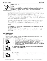
 

Prior to Start-Up 


NOTE

 - If it is necessary to perform a pressure test, prior to initial use to ensure pump is functioning properly, then the 

following criteria should be maintained for this test: 


1.  Have a professional perform this test.   
2.  Ensure all pump and system components are sealed properly to prevent leaks.   
3.  Remove any trapped air in the system by fully opening filter manual air relief valve until a 

steady stream of water (not air or air and water mix) is discharged from the valve. 

4.  Allow no more than 50 psi (345 kPa) at a water temperature no higher than 100

°

 F (38

°

 C).   

5.  Run pressure test for no longer than 24 hours.  Immediately inspect all parts to verify they are 

intact and functioning properly.   
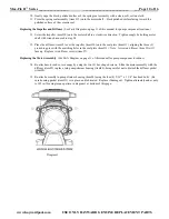
 

  WARNING –


If pump is being pressure tested (50 PSI MAXIMUM), be sure pressure 

has been relieved prior to removing cover.


  WARNING – 

All suction and discharge valves 

MUS

T be 

OPE

N, as well as filter air relief 

valve (if available) on filter, prior to starting the circulating pump system.  Failure to do so could result in 
severe personal injury.   


Summary of Contents for Max-Flo™

Page 1: ...122 degrees F an elevated base for improved motor cooling and to prevent flooding The Max Flo II is an ideal choice for both new construction or as a replacement pump To prevent potential injury and t...

Page 2: ...nnot be readily disassembled for storage A storable pool is constructed so that it is capable of being readily disassembled for storage and reassembled to its original integrity Though this product is...

Page 3: ...outlets and or suction outlet covers which are damaged broken cracked missing or unsecured cause severe injury and or death due to the following entrapment hazards Hair Entrapment Hair can become ent...

Page 4: ...operate pool and spa circulation system if a system component is not assembled properly damaged or missing Do not operate pool and spa circulation system unless filter air relief valve body is in loc...

Page 5: ...o meet all local and national codes Fasten pump to base or pad with screws or bolts to further reduce vibration and stress on pipe or hose joints The base MUST be solid level rigid and vibration free...

Page 6: ...s Use care when using Teflon tape as friction is reduced considerably do NOT over tighten fitting or you may cause damage If leaks occur remove connector clean off old Teflon tape re wrap with one to...

Page 7: ...mming pool spa or hot tub and to all electrical equipment metal piping except gas piping and conduit within 5 ft 1 5 m of inside walls of swimming pool spa or hot tub Wiring WARNING All electrical wir...

Page 8: ...uction pipe If pump does NOT prime within five minutes stop motor and determine cause Be sure all suction and discharge valves are open when pump is running See Troubleshooting Guide ATTENTION Wait fi...

Page 9: ...4 exposing the diffuser item 9 Remove the two diffuser screws item 7 and pull the diffuser off of the seal plate item 13 to expose the impeller item 10 Removing the Impeller See Parts Diagram on page...

Page 10: ...the diffuser item 9 over the impeller item 10 onto the seal plate item 13 aligning the three 3 protruding pins with the matching holes in the seal plate item 13 Note Arrow on diffuser item 9 will face...

Page 11: ...USE ONLY HAYWARD GENUINE REPLACEMENT PARTS Max Flo II Series __________________ ____________________________ Page 11 of 16 Replacement Parts Parts Diagram SEE PARTS LISTING ON NEXT PAGE Item 16 Option...

Page 12: ...thru 1 HP 1 SPX2700BE Diffuser 2 HP 1 10 SPX2700C Impeller for HP Max Rate Pump 10 SPX2707CM Impeller for 1 HP Max Rate Pump 10 SPX2710CM Impeller for 1 HP Max Rate Pump 10 SPX2715CM Impeller for 2 HP...

Page 13: ...mp strainer housing is filled with water and cover o ring is clean Ensure o ring is properly seated in the cover o ring groove Ensure o ring is lubricated with Jack s 327 and that strainer cover is lo...

Page 14: ...ir leak in suction piping cavitations caused by restricted or undersized suction line or leak at any joint low water level in pool and unrestricted discharge return lines Solution Correct suction cond...

Page 15: ...g the warranty period except as a result of freezing negligence improper installation use or care shall be repaired or replaced at our option without charge within 90 days of the receipt of defective...

Page 16: ...www haywardpool com USE ONLY HAYWARD GENUINE REPLACEMENT PARTS Max Flo II Series ___ Page 16 of 16 This Page is Blank...

Reviews: