background image


1.47 

1.47

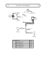
ELECTRICAL CIRCUIT DIAGRAM

Black

Black

Stop  Switch

(Mounted  on  handlebar)

Control
Module

Stop  Switch

Wire

Red

Red

Engine  Stop

Switch  Wire

Engine  Stop

Switch

(Mounted  On  

Engine)

Engine  Stop

Switch  Wire

Red

Black

On

OFF

Yellow

Yellow

Switch  Link  Wire

Red

Transmission

Microswitch

Cutter  Clutch

Microswitch

Blue

Red

Blue

4

6

5

1

2

7

Item No. Description

Part No.

1

Switch Assembly C/W Keys

510224

2

Control Module Assy

111-5820

4

Cable Assy Microswitch

510116

5

Cutterclutch Microswitch

510068

6

Transmission Microswitch

510069

7

Cable Assy Engine Stop

510227

Summary of Contents for CONDOR 510D

Page 1: ... POWER UNIT Model No 510D Serial No from 312030001 ATTACHMENTS Serial No from 312030001 Verge Attachment 3 Blades Code 214D Verge Attachment 5 Blades Code 243D Rotary Attachment 30 Code 212D Operator s Manual Original Instructions EN Date 20 02 2012 ...

Page 2: ......

Page 3: ...ORE USING THE CONDOR HYDROSTATIC DRIVE MOWER IT IS ESSENTIAL THAT OPERATORS STUDY IT FOR THEIR OWN SAFETY ALL OPERATORS SHOULD SEEK AND OBTAIN PROFESSIONAL AND PRACTICAL INSTRUCTIONS ON THE SAFE USE OF THE MOWER THESE SERVICES ARE AVAILABLE THROUGH HAYTER APPROVED COMMERCIAL DEALERS ...

Page 4: ......

Page 5: ...cants And Hydraulic Fluids 1 18 Verge Attachments 1 18 Rotary Attachments 1 18 Assembling The Mower 1 19 1 21 Assembling and Removing the Cutterhead Attachments Introduction 1 19 Assembling the Cutterhead to the Power Unit 1 20 1 21 Operating The Mower 1 22 1 28 Safety Notice 1 22 Operator Presence Controls 1 22 Identification of Controls 1 23 Braking System 1 23 Throttle Control 1 23 Travel 1 23 ...

Page 6: ...0 1 31 Daily and before use 1 31 1 33 Every 50 hours 1 34 Every 200 hours 1 35 1 37 Rotary Attachment 1 41 1 42 Cutterblades 1 42 Preparing the Mower for Storage 1 43 GRASS CUTTING FAULTS Both Types of Attachments 1 44 TROUBLE SHOOTING 1 45 1 46 ELECTRICAL CIRCUIT DIAGRAM 1 47 WARRANTY 1 48 NOTES 1 49 1 50 CUSTOMER INFORMATION 1 51 ...

Page 7: ...tical instruction Such instruction should emphasise The need for care and concentration when working with this machine Preparation Check that the machine complies with all applicable regulations including those in force when used on the public highway While mowing always wear substantial footwear and long trousers Do not operate the equipment when barefoot or wearing open sandals Eye protection sh...

Page 8: ...et grass where feasible Walk never run Do not use on slopes of more than 20 degrees Always be sure of your footing on slopes and stay alert for humps hollows and other hidden hazards Ground conditions may affect the ability of the operator to maintain safe footing Particular conditions may not permit safe operation on the slope limit stated Mow across the face of the slopes never up and down Exerc...

Page 9: ...harge chute Before cleaning checking or working the mower After striking a foreign object Inspect the mower for damage and ensure necessary repairs are made before re starting If the mower starts to vibrate abnormally check immediately Stop the engine turn the ignition control to the off position set the parking brake Whenever you leave the mower Before refuelling Before making a height of cut adj...

Page 10: ...tdoors Be careful during adjustment of the machine to prevent entrapment of the fingers between moving blades and fixed parts of the machine On twin bladed cutterheads take care as rotating one bottom plate will cause the other to rotate Health Safety The Condor Mower has been designed and constructed so that in so far as is reasonably practical they meet the safety requirements of the Machinery D...

Page 11: ... run switch E Stop engine and remove spark plug lead before performing maintenance or repair work F Parking break grip a latch lever to engage the parking brake Unlatch and release lever to disengage the parking brake G Engine speed control push the lever forward to increase engine speed pull the lever back to reduce engine speed H Engage cutterhead drive I Disengage cutterhead drive J WARNING CAU...

Page 12: ...of unit 214D 243D Decal Cylinder cut adjustment Part No 214053 0 Location Top front of verge unit both sides Decal Severing of hand of fingers Part No 40 13 010 1 Location Both sides of the deck 212D R H side of deck 214D R H side of deck 243D Decal Cutterhead timing Part No 111 3904 A Location Between gearboxes on the rotary attachment ...

Page 13: ...o physical agents noise Vibration Levels Operator Daily Personal Vibration Exposure HAYTER LIMITED have no control over site condi tions duration of use state of maintenance or adjustment of the mower All of these factors will affect the opera tor s daily personal vibration exposure level Under certain working conditions the operator may be exposed to vibration levels above those stated EC Declara...

Page 14: ...ment for use outdoors as amended and the regulations Also Directive 2004 108 EC Electromagnetic Compatibility and the regulations transposed into national law transposed into national law Procedure applied for the conformity assessment ANNEX VI procedure 1 Notified Body Sound Research Laboratories Ltd Holbrook House Little Waldingfield Sudbury Suffolk CO10 0TH ENGLAND Notified body identification ...

Page 15: ...and has separate clutch controls for engaging the cutterhead and ground drives The Condor system is well balanced and incorporates a number of features for effortless safe mowing The handle bar controls are user friendly and incorporate an operator presence control system This system will automati cally disengage the cutterhead and ground drive clutches when the operator releases the controls The ...

Page 16: ...res Fuel Type Unleaded petrol Fuel Capacity 6 1 Litres IMPORTANT PREVENT DAMAGE For further information regarding the engine refer to the Engine Manual Transmission System Drive Type Hydraulic static differential transaxle Cutterhead Drive System Power Unit Intermediate Drive Single clutch V belt drive with integral engine lockout switch sensor Power Unit Final Drive Twin V belt via countershaft V...

Page 17: ...ive Hand operated lever to engage Maintain by twin hand operator pressure control levers Engine Speed Hand operated lever Parking Brake Hand operated lever with engagement lock Forward and Reverse Forward and reverse twin hand operator hand thumb levers Ignition On Off switch Bypass Valve Hand operated lever Weight and Dimensions 30 Rotary attachment fitted 30 Verge attachment fitted Maximum Worki...

Page 18: ...ydraulic components and invalidate warranty Verge Attachments Code 214D Code 243D Cylinder Drive V Belt Countershaft V Belt Countershaft Cutting Width 762 mm 762 mm Cylinder Diameter 190 mm 190 mm Cylinder Speed 1250 rpm 1250 rpm Height of Cut 17 mm 0 7 to 62 mm 2 4 17 mm 0 7 to 62 mm 2 4 Number of Blades 3 5 Smooth Rear Roller Standard Standard Rotary Attachments Code 212D Drive V Belt Gearbox Cu...

Page 19: ... 214D and 243D Any of these attachments can be quickly mounted to or removed from the power unit WARNING PREVENT ACCIDENTS Stop the engine apply the parking brake and disconnect the spark plug lead before attempting to remove or mount a cutterhead attachment WARNING PREVENT ACCIDENTS Do not attempt to carry out the following procedure by your self another person must assist you Power unit with 30 ...

Page 20: ...e power unit to the cutterhead mountings and connect up using the two bolts washers and nyloc nuts items 3 4 5 Do not fully tighten bolts at this stage Refer to Fig 1 Note The rotary attachment has two mounting holes Assemble using the right hand holes Refer to Fig 2 item A 9 Adjust the two tensioning bolts item 2 Fig 1 equally to tension the twin drive belts The bolts are correctly tensioned when...

Page 21: ...s the microswitch wires with a cable tie 16 From the microswitch bracket route the cable to follow the cutter clutch cable up the left hand handlebar to the anchor bracket and secure the cable adjuster into the bracket using the two nuts provided refer to MAINTENANCE RUNNING IN PERIOD AT FIRST 50 HOURS OF USE CHECK CUTTERHEAD BRAKE CABLE ADJUSTMENT 17 Remove the pushfix which is secured to the eye...

Page 22: ... releasing hold of the handlebars for whatever reason Each handlebar is provided with an OPC lever and these are mechanically linked such that operation or either will activate the system These levers are lightly spring loaded and are held down by the palm of the hand during operation Release of the OPC levers will cause the cutterhead clutch to disengage activating the brake to arrest the rotatio...

Page 23: ...rward and reverse travel controls are released or the engine speed is reduced service braking occurs to reduce the travel speed WARNING PREVENT ACCIDENTS The service braking system will not hold the mower at a standstill ALWAYS ensure that the park ing brake is engaged to park the mower at a standstill Throttle Control Operate the throttle control forwards to in crease the engine speed Operate the...

Page 24: ...travel rocker lever and it will automatically return to the neutral position thereby causing the mower to come to a standstill Adjustment of travel rocker levers Both LH and RH travel rockers levers are adjustable for operator comfort To adjust slacken the appropriate bolt 1 and move the lever assembly 3 in the required direction Retighten the clamp bolt securely before operating machine Transmiss...

Page 25: ... of either or both will keep the system activated To disengage cutterhead drive Release the OPC levers Observe that the cutterhead clutch control lever automatically returns backwards to the disen gaged position WARNING PREVENT ACCIDENTS Do not operate the mower if the handlebar controls of the operator presence control system are defec tive in any way ALWAYS replace faulty parts and check that th...

Page 26: ...o not allow the start grip to snap back against the engine Return it gently to prevent damage Starting a warm engine Follow the procedure for Starting a cold engine except the use of the choke will not normally be required when starting a warm engine Stopping the Engine To stop the engine Turn the ignition key to the off A position In normal use bring the mower travel to a stop disengage the cutte...

Page 27: ...ro contact with the cutting cylinder 4 Rotary attachment Ensure that the cutterblade and bottom plates are maintained in good condition 5 Always disengage the cutterhead drive when transporting across ungrassed areas Verge attachment Grass will lubricate the cutting edges in work Excess heat will build up if the cutting cylinder is run out of work which will cause rapid wear to place For this reas...

Page 28: ...ent The height of the handlebar may be adjusted at the connection between the handlebar stays 1 and the plate on the handlebar 2 Adjustment holes 3 provide 3 alternative handlebar settings Ensure that the handlebars are set at the same level on each side of the mower Note The length of the connecting rods to the travel control rocker levers must be re adjusted as necessary to ensure correct operat...

Page 29: ...ervice intervals are based on normal operating conditions Severe or unusual con ditions will necessitate shorter service intervals WARNING PREVENT ACCIDENTS Remember the engine and transmission oil is hot after mower use Allow to cool before carrying out maintenance procedures WARNING PREVENT ACCIDENTS Use hazardous substances carefully The following fluids are identified as being hazardous Substa...

Page 30: ...tain 3mm free movement of the cable Retighten the locknut Note The cutterhead drive clutch cable adjuster is positioned to the left of the cutterhead brake adjuster when fitted with a rotary cutterhead attach ment Check belt guide clearance Engage the cutter head drive and check the clearance between the belt guides and the belt as shown If adjustment is required slacken the idler pulley mounting ...

Page 31: ...aner Dual element type Check the air cleaner elements for holes or tears and replace if damaged Clean the paper element CAUTION PREVENT DAMAGE Always replace a damaged air cleaner or damage to the engine will result NEVER run the engine with out the air cleaner correctly fitted Check fuel level Top up as necessary with unleaded petrol Always top up before storing the mower over night to prevent wa...

Page 32: ...peration at a low fluid level may result in permanent internal damage Check the operator presence controls Stop the engine Check the operation of the microswitches ensure the operation arm is free of any debris and that the roller rotates freely Spray the hydrostatic unit neutral detent microswitch with a water repellent lubricant Engage the cutterhead drive and operate the OPC levers The engine s...

Page 33: ...BOTTOM BLADE ADJUSTMENT Rotary attachment Check the condition of the cutterblades and mounting arrangement for signs of wear damage or looseness Ensure that the cutterblades are not bent or cracked and that the cutterblade securing bolts are tight Damaged or excessively worn cutterblades may be out of balance which will cause excessive vibration this may lead to breakage or result in serious damag...

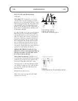
Page 34: ...cessary with the correct grade of transmission fluid refer to SPECIFICATIONS Top up fluid should be introduced through the dip stick tube Cutterhead Gearbox Rotary Attachment Remove filler plug on top of the gearbox and check oil level Gearbox should be 3 4 full If nec essary top up with the correct grade of oil refer to SPECIFICATIONS General Lightly apply a good quality general purpose lubricati...

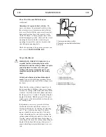
Page 35: ... actuating lever by removing the 5 16 UNF hex nut and spring washer Slacken the main engine drive belt by loosening the jockey pulley bracket Remove the UNC Setscrew and retaining washer and remove the fan Remove the 4 mounting bolts and support the hydrostatic unit Remove the connecting pipe from the top of the hydrostatic unit and allow the residual oil to drain into a suitable can Lift the unit...

Page 36: ...OD Reconnect the connecting pipe Reconnect the ball joint to the actuating lever Replace lower cover and fan guard screen Do not replace the plastic reservoir at this stage Remove the bleed plug from the top of the hydrostatic unit Top up through the reservoir base until oil flows from the bleed plug aperture and keep topped up during the following procedure WARNING PREVENT ACCIDENTS Do not procee...

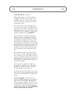
Page 37: ...nit General Maintenance Transmission bypass valve The lever should be adjusted so that the bypass valve plunger on the hydrostatic unit is fully depressed when the lever is just touching the handlebar cross tube To adjust setting slacken adjuster nuts at end of cable Adjust cable setting and lock the adjuster nuts Check that the machine can be moved with the engine switched off when the bypass val...

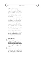
Page 38: ...i tion is reached Repeat this procedure for reverse travel except move the adjuster screw to stop the actuating lever 5mm before the extreme full travel position is reached Tighten the locknuts IMPORTANT PREVENT DAMAGE The hydrostatic unit may sustain permanent damage if the forward and reverse stops allow greater travel than the limits indicated Neutral detent mechanism Should the mower creep for...

Page 39: ...t the following procedure before commencing work and re check the settings every few hours Check that the cutting cylinder is correctly set to the bottom blade by holding a thin piece of paper between the cutting cylinder and the bottom blade as shown Carefully rotate the cylinder and check that the paper is cut cleanly at all points along the length of the blade Hold the paper at 90 degrees right...

Page 40: ...cessive expansion to take place which will further aggra vate the situation by increasing the contact pres sure If the cutterhead is allowed to operate for more than a few hours without adjustment the running wear will eventually cause the cylinder to run out of contact with the bottom blade At this stage very rapid rounding of the cutting edges will occur as grass and abrasive particles pass thro...

Page 41: ...steners to the same torque by working from the centre out towards the blade ends The new bottom blade must be ground on its hold er prior to refitting to the cutterhead Adjust the cutting cylinder position to give ade quate clearance for fitting the new bottom blade holder Refit the bottom blade holder assembly using new fixing bolts and tighten securely Finally adjust the cylinder to the bottom b...

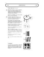
Page 42: ...age Ensure that the cutterblades are not bent or cracked Regularly check that the bolts securing the cut terblades and bottom plate are secure To remove the cutterblades Remove the cutter blade nut 2 and bolt 5 How to assemble the cutterblades Assemble cut terblades 4 such that they are below and pointing away from the bottom plate 1 Tighten the cut terblade nuts 2 and bolts 5 to a torque of 19Nm ...

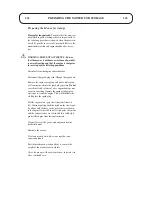
Page 43: ... engine oil into the spark plug aperture Do not exceed the stated volume of oil as engine damage may occur on restarting Operate the engine start grip sev eral times to crank the engine This will distribute the oil Replace the spark plug Pull the engine start grip slowly until resistance is felt Continue pulling until the notch on the starter pul ley aligns with the hole on the recoil starter as s...

Page 44: ...act with the bottom blade Re adjust cutting cylinder to the bottom blade Cutting cylinder is in heavy contact with the bottom blade Re adjust cutting cylinder to the bottom blade Height of cut is too high Lower the height of cut setting Cutting edges of cutting cylinders bottom blades are rounded Re grind to restore the cutting edges Lines of uncut or badly cut grass in direction of travel Tram li...

Page 45: ...the on position Insufficient choke Reset the choke lever For all other engine problems refer to ENGINE HANDBOOK Lack of transmission drive Parking brake engaged Release parking brake Low oil level Fill reservoir to correct level Air in system Carry out bleeding procedure Incorrect oil used Drain reservoir and refill with correct oil Drive belt incorrectly tensioned Re tension drive belt Broken dri...

Page 46: ...drive belt Incorrect cutterhead drive clutch adjustment Re adjust as necessary After initial satisfactory operation the machine loses power Worn hydrostatic unit Replace as necessary Hydrostatic unit oil level low Fill reservoir to correct level Incorrect oil viscosity Drain system and refill with correct grade of oil Air in hydrostatic unit Carry out bleeding procedure Overheating Refer to TRANSM...

Page 47: ...ine Engine Stop Switch Wire Red Black On OFF Yellow Yellow Switch Link Wire Red Transmission Microswitch Cutter Clutch Microswitch Blue Red Blue 4 6 5 1 2 7 Item No Description Part No 1 Switch Assembly C W Keys 510224 2 Control Module Assy 111 5820 4 Cable Assy Microswitch 510116 5 Cutterclutch Microswitch 510068 6 Transmission Microswitch 510069 7 Cable Assy Engine Stop 510227 ...

Page 48: ...ire basis This warranty which is not capable of assignment does not apply to any unit that has been tampered with altered misused or abused and will become invalid if non genuine Hayter parts are fitted This warranty does not cover minor adjustments unless they are due to defective materials or workmanship Consult the own ers handbook or your authorised Hayter dealer for assistance when making the...

Page 49: ...1 49 1 49 NOTES ...

Page 50: ...1 50 1 50 NOTES ...

Page 51: ...1 51 1 51 CUSTOMER INFORMATION Machine Details Engine Serial No Hydrostatic Unit Serial No Transaxle Serial No P U Serial No Verge Attachment Serial No Rotary Attachment Serial No ...

Page 52: ......

Reviews: