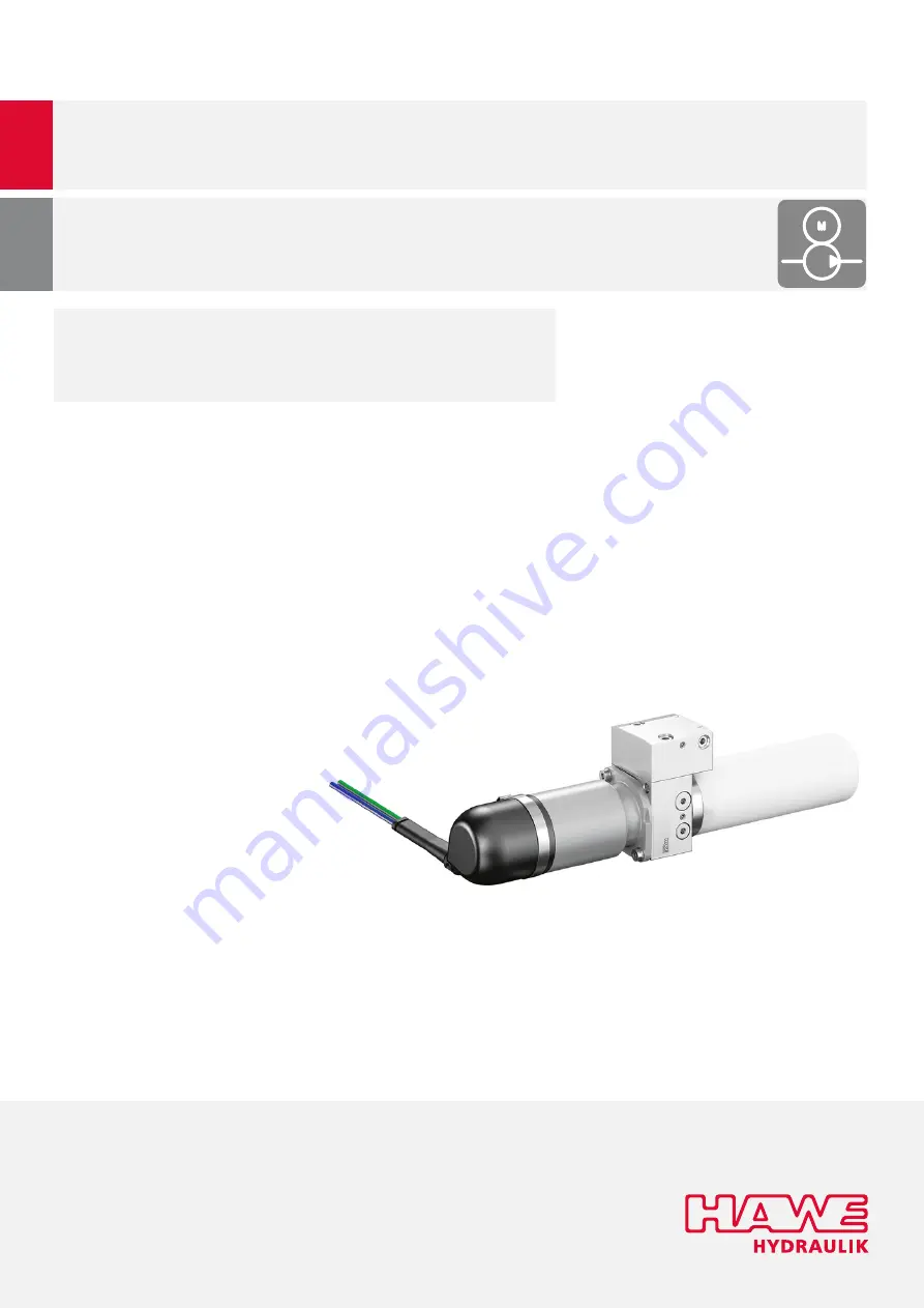
Mini hydraulic power pack type HR 050
Original assembly instructions
B 601407-2021 -1.0 en
Operating pressure p
max
:
Flow rate Q
200 bar
0.95 l/min
Page 1: ...Mini hydraulic power pack type HR 050 Original assembly instructions B 6014 07 2021 1 0 en Operating pressure pmax Flow rate Qmax 200 bar 0 95 l min...
Page 2: ...Brand names product names and trademarks are not specifically indicated In particular with regard to registered and protected names and trademarks usage is subject to legal provisions HAWE Hydraulik r...
Page 3: ...ery 13 4 3 Storage 14 5 Assembly and installation 15 5 1 Mechanical connection 15 5 2 Electrical connection 15 5 3 Hydraulic connection 16 6 Start up 18 6 1 Switching the hydraulic system on off 18 7...
Page 4: ...for the machine manufacturer and machine operator as well as for training courses 1 2 Safety instructions and symbols Safety indication In these instructions the following warning and safety notes are...
Page 5: ...and of the Council of 18 December 2006 concerning the Registration Evaluation Authorisation and Restriction of Chemicals REACH establishing a European Chemicals Agency amending Directive 1999 45 EC a...
Page 6: ...ovements in relation to machinery DIN EN ISO 14118 Safety of machinery Prevention of unexpected start up DIN EN ISO 4413 Hydraulic uid power General rules and safety requirements for systems and their...
Page 7: ...hinery Directive 2006 42 EC and is intended exclusively for installation in a machine or system The product is controlled via the manufacturer s machine plant control Comply with the manufacturer s op...
Page 8: ...devices the product still poses residual risks Observe the safety instructions in this manual to reduce health hazards and avoid dangerous situations The operator must ensure that the operating condit...
Page 9: ...ional training knowledge and experience so that he she can recognize and avoid dangers that can be caused by electricity Auditor Persons of a technical inspection body who are authorized to perform te...
Page 10: ...ersion pressure limiting valves for safeguarding against overpressure through the pump Comfort version thermal safety valves for limiting the overpressure from outside for the holding function pressur...
Page 11: ...k valve to consumer port B Emergency manual actuation only Comfort version The system can be switched to a pressureless state using the emergency manual valve CAUTION Injuries due to cylinders droppin...
Page 12: ...against excessive pressure Hydraulic uid ows back to the tank DAMAGE Malfunction of the check valves due to leaking pressure limiting valves Basic version If actuated frequently con gurable pressure l...
Page 13: ...f the completely assembled units includes hydraulic power pack Hydraulic uid is not included in the scope of delivery 4 2 Checking the delivery Unpacking 1 Remove product 2 Check product for transport...
Page 14: ...e it so it is dry and free of dust Protect against sunlight UV radiation Storage temperature between 30 C and 80 C Do not store near sources of ignition or heat aggressive media e g acids fuels or lub...
Page 15: ...ons align correctly 3 Attach the hydraulic power pack using the two M6 threads with a maximum torque of 7 Nm 4 After a week of operating time at the latest check the ttings 5 2 Electrical connection D...
Page 16: ...iled components may cause system failure and irreparable damage Clean the workspace before connecting the hydraulic system Clean hydraulic components before connecting the hydraulic system Only use hy...
Page 17: ...The level of the hydraulic uid should be within the cross marking 5 Gently shake the hydraulic power pack so that the air bubbles pass into the tank Wait a few hours until all the air bubbles are in t...
Page 18: ...ck the hydraulic power pack has been connected correctly mechanically ange hydraulically hose lines hydraulic uid electrically wiring power supply control xed installation attachment to the machine in...
Page 19: ...instructions provided in this section Observe the following safety instructions additionally to the safety instructions in chapter For your safety 7 1 Maintenance plan Failure of hydraulic systems Fai...
Page 20: ...tank 150 mm 300 ml Max usable tank volume tank 60 mm 82 ml tank 150 mm 228 ml 7 2 3 Replacing the hydraulic uid The hydraulic system is switched off and secured against unintentional restart The syst...
Page 21: ...tightening torque of 6 2 Nm 10 Vent the hydraulic system using the venting provisions on the consumer 11 Correctly dispose of the hydraulic uid hydraulic uid container and any cloths contaminated wit...
Page 22: ...draulic components 7 Properly dispose of all disassembled parts Disposal Dispose of hydraulic uid and system components as follows Dispose of hydraulic uid packaging containers soaked cleaning cloth e...
Page 23: ...t HAWE consumer does not move motor faulty There is voltage present but the motor does not work Replace the hydraulic power pack supply voltage too low Measure voltage directly on the motor Restore po...
Page 24: ...nternal thread and banjo bolts Ambient temperature 30 to 80 C 10 1 2 Operating conditions Service life 300 operating hours in periodic intermittent operation exception Q04 from 150 bar only 100000 cyc...
Page 25: ...lerance 10 10 1 4 Electrical data Motor 12 V DC Voltage 12 V DC Current consumption see characteristic lines max 45 A Overload protection temperature switch Power Q02 372 W Q04 540 W Duty cycle interv...
Page 26: ...10 2 Circuit diagram 10 2 1 Circuit diagram BASIC COMFORT 26 27 B 6014 07 2021 1 0 HAWE Hydraulik SE...
Page 27: ...lectronic components are perfectly coordinated with the hydraulic components and simplify ing control signal evaluation and fault detection The intelligent system solutions reduce energy consumption a...