Setting Up the Bases
1
Setting Up the Bases
Setting Up the Bases
www.HavahartWireless.com
1-800-800-1819, OPTION 453
1
3
4
Setting Up the Bases
1
•
Look outside your home: DO NOT place Bases within 3 feet of electric power meters,
air conditioning units, downspouts, or large trees or bushes immediately outside the
wall. Move the Bases so that they have a clear, direct line of sight to the desired Fence
Boundary.
•
Position Master Base A on the inside surface of an exterior wall. Using the removable
adhesive strips, mount your Base on the wall. Plug it in at this time. A solid green light will
appear on the Master Base A indicating it is on. Master Base A will beep once, indicating it
is powered on.
•
Identify the locations for the additional bases (labeled B, C and D). These locations must
be a minimum of 20 feet apart, mounted in a clockwise fashion in alphabetical order.
Measure the 6 distances between the bases and use the chart below to record your
measurements.
•
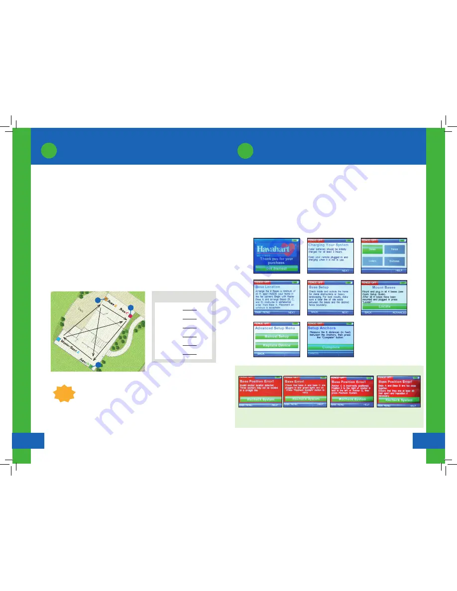
As shown in Illustration B, attach bases, in alphabetical and clockwise order:
Screen 1.0
Screen 1.2
Screen 1.5
Screen 1.6
Screen 1.7
Make sure your Controller and Batteries are fully charged before you start.
Activating the Bases:
•
Touch the screen of the Controller to turn it on and press “Get Started” (see Screen 1.0).
•
A “Charging Your System” screen will appear. Press “Next” (see Screen 1.1).
•
Press “Bases” (see Screen 1.2).
•
Two screens will appear to help in placing your Bases. Press “Next” after each (see Screens 1.3
and 1.4).
•
Press “Locate” (see Screen 1.5).
•
Select “Manual Setup” from the Advanced Setup Menu (see Screen 1.6).
•
See the Instruction Manual for more information and complete screen shots:
www.havahartwireless.com/resource/uploads/custom-select-instruction-manual.pdf
Screen 1.1
Screen 1.3
Screen 1.4
MEASUREMENT CHART
A
to
B
:
B
to
C
:
C
to
D
:
D
to
A
:
A
to
C
:
B
to
D
:
feet
feet
feet
feet
feet
feet
TIP:
For easier measurements, go outside the home to measure
distances between bases.
Activate the Bases in a clockwise fashion.
Illustration B
2
3
4
ERROR SCREENS
Error Screen 1.0a
Bases are too close together.
Error Screen 1.0c
Bases not placed in correct
order.
Error Screen 1.0b
Bases have too much signal
limiting material between them.
Error Screen 1.0d
The Bases are located too close
to one another and must be
placed farther apart.
1. Master Base
A
2. Base
B
3. Base
C
4. Base
D