background image

36

 OPERATING INSTRUCTIONS


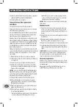
2) Loosen the mitre lock (25).

3) Rotate the mitre table (21) until the pointer

aligns with the desired angle.

4) Retighten the mitre lock (25).

WARNING

. Be sure to tighten the mitre  lock

before making a cut. Failure to do so could result
in the table moving during the cut and cause
serious personal injury.

5) Place the workpiece flat on the table with

one edge securely against the fence (19). If
the board is warped, place the convex side
against the fence. If the concave side is placed
against the fence, the board could break and
jam the blade.

6) When cutting long pieces of timber, support

the opposite end of the timber with the side
support bars (37), a roller stand or a work
surface that is level with the saw table.

7) Use the clamp assembly (10) to secure the

workpiece wherever possible.

8) It is possible to remove the clamp assembly

(10) by loosening the clamp assembly lock
(11) and moving it to the other side of the tab-
le. Make sure the clamp assembly lock is tight
before using the clamp.

9) Before turning on the saw, perform a dry run

of the cutting operation to check that there
are no problems.

10) Hold the operating handle (7) firmly and

squeeze the switch trigger (24). Allow the
blade to reach maximum speed and slowly
lower the blade into and through the work-
piece.

11) Release the switch trigger (24) and allow the

saw blade to stop rotating before raising the
blade out of the workpiece.Wait until the
blade stops before removing the workpiece.

Cross-cutting (with slide action)

When cutting wide workpieces, first unscrew the
slide lock (29).

1) Pull on the release knob (6), raise the saw arm

(5) to its highest position and slide it towards
you.

2) Hold the handle firmly and squeeze the

switch trigger (24). Allow the blade to reach
maximum speed.

3) Slowly lower the blade into the workpiece

and slide it away from you at the same time
until the workpiece is cut.

4) Release the switch trigger (24) and allow the

saw blade to stop rotating before raising the
blade out of the workpiece.Wait until the
blade stops before removing the workpiece.

Bevel cut

A bevel cut is made by cutting across the grain
of the workpiece with the blade angled to the
fence and mitre table.The mitre table is set at
the zero degree position and the blade set at an
angle between 0º and 45º.

Use the slide action when cutting wide work-
pieces.

1) Pull on the release knob (6) and lift the saw

arm to its full height.

2) Loosen the mitre lock (25).

3) Rotate the mitre table (21) until the pointer

(22) aligns with zero on the mitre scale .

4) Retighten the mitre lock (25).

WARNING.

Be sure to tighten the mitre lock be-

fore making a cut. Failure to do so could result in
the table moving during the cut, causing serious
personal injury.

5) Loosen the bevel lock (16) and pull out the 0º

bevel adjuster. Move the saw arm (5) to the
left or right to the desired bevel angle (bet-
ween 0º and 45º).Tighten the bevel lock (16).

6) Place the workpiece flat on the table with

one edge securely against the fence (19). If
the board is warped, place the convex side
against the fence. If the concave side is placed
against the fence, the board could break and
jam the blade.

7) When cutting long pieces of timber, support

the opposite end of the timber with the side
bars (36), a roller stand or a work surface that
is level with the saw table.

8) Use the clamp assembly (10) to secure the

workpiece wherever possible.

9) It is possible to remove the clamp assembly

EN

Summary of Contents for 5969001

Page 1: ...NS 1 866 206 0888 Our Customer Service staff is ready to provide assistance In the case of a damaged or missing part most replacement parts ship from our facility For immediate help with assembly or for additional product information call our toll free number 1 866 206 0888 Notre personnel du Service à la clientèle est disponible pour vous aider Dans le cas d une pièce endommagée ou manquante la p...

Page 2: ...S F LISTEDESCOMPOSANTES p 3 DESCRIPTION CARACTÉRISTIQUESETCONSIGNES DIRECTIVESDESÉCURITÉGÉNÉRALES PRÉCAUTIONSADDITIONNELLESPOURSCIESÀONGLETS p 6 CONSEILSD UTILISATION p 11 SCHÉMAETLISTEDESPIÈCES p 19 p 7 p 8 GARANTIE p 22 ...

Page 3: ...tège lame rotatif 13 Bras rétractable 14 Couvre boulon de la lame 15 Sac à poussière 16 Verrouillage de biseau 17 Échelle de biseau 18 Réglage du biseau à 0 19 Guide 19A 19B Support de butée 20 Clé hexagonale 5 mm 21 Table à ong 22 Indicateur de l échelle d onglets lets 23 Insertion de table trait de coupe 24 Interrupteur 25 Verrou des onglets 25A Bouton de verrouillage 26 Verrouillage de l arbre ...

Page 4: ...45 droite 35 Vis de réglage du biseau à 0 36 Barres latérales de support x2 37 Trous pour barres latérales de support 2 ens 38 V intérieur is d arrêt pour barres latérales de support 39 Barre stabilisatrice 40 Bride 41 Bouton d arrêt pour barres latérales de support 42 Lame de scie 43 Affichage d état de marche 44 Éclairage du poste de travail 8 17 24 12 25 31 36 14 30 28 15 27 39 11 36 10 22 25A 9...

Page 5: ...5 LISTE DES COMPOSANTES B9 4 B3 2 43 B2 30 32 31 B4 B5 B6 B7 B8 42 F ...

Page 6: ...té pour faisceaux laser AVERTISSEMENT Ne regardez pas directement à l intérieur du faisceau laser AVERTISSEMENT Il peut être plus difficile de voir le faisceau laser dans un endroit très ensol eillé ou sur certaines surfaces Des risques peuvent survenir si vous regardez délibérément à l intérieur du faisceau Veuillez observer les directives suivantes s Le laser doit être utilisé et entretenu confor...

Page 7: ...e utilisez une rallonge de calibre supérieur Plus le numéro du calibre est petit plus la rallonge est puissante 10 Portez un équipement approprié Ne portez pas de vêtements amples des gants crava tes bracelets ou autres bijoux qui pourraient se prendre dans des pièces en mouvement Des chaussures antidérapantes sont recom mandées Attachez les cheveux longs 11 Portez toujours des lunettes de sécurit...

Page 8: ...saire ne branchez PAS le conducteur de mise à la terre à une source d électricité 4 Vérifiez auprès d un électricien qualifié ou un technicien de service si vous ne comprenez pas complètement les instructions de mise à la terre ou si vous n êtes pas sûr de la sécurité de votre installation électrique 5 Utilisez seulement une rallonge à trois fils ayant une prise avec mise à la terre ainsi qu un récep...

Page 9: ...igneu sement la pièce à couper et retirez les clous ou autres objets avant de commencer à couper s Ne tentez pas de retirer des copeaux ou mor ceaux coupés en passant la main par dessus ou au dessous de la lame s rrêtez toujours l outil avant de libérer une lame coincée s E tentez pas de ralentir ou d arrêter la lame à l aide d un morceau de bois Laissez la lame s arrêter d elle même s Si vous ête...

Page 10: ...DIMENSIONS RECOMMENDÉES POUR LES RALLONGES Ampérage de l outil Tension Longueur totale du fil en pieds Calibre de la rallonge en A W G minimum 25 pi 50 pi 100 pi 150 pi 3 6 120V 18 16 16 14 6 8 120V 18 16 14 12 8 10 120V 18 16 14 12 10 12 120V 16 16 14 12 12 16 120V 14 12 PRÉCAUTIONS ADDITIONNELLES POUR SCIES À ONGLETS Rallonges électriques s Remplacez immédiatement les rallonges endommagées L util...

Page 11: ...ar les protège lames Utilisez plutôt la poignée de transport 8 Transport Soulevez la scie à onglets seulement lorsque le bras est en position de verrouillage abaissé et que la scie n est pas en marche ni sous tension Soulevez la scie par la poignée de transport 8 ou la base Ne soulevez pas la scie par les protège lames ou la poignée d opération 7 Installation sur établi La base de la scie est trou...

Page 12: ... position verticale il arrêtera automatiquement à la position du bi seau 0 Resserrez le verrouillage du biseau 16 Les brides de fixation 10 peuvent être instal lées sur le guide ou de chaque côté de la lame selon la tâche effectuée Utilisez le verrou des brides de fixation 11 à l arrière du guide pour fixer les brides solide ment en position Bouton de verrouillage de l arbre Le bouton de verrouillage...

Page 13: ...sez le bras de la scie 5 à la position la plus basse et appuyez sur le bouton de CONSEILS D UTILISATION relâchement 2 pour placer le bras de la scie en position de transport 3 Desserrez le verrou des onglets 25 et ap puyez sur le bouton de verrouillage 25A 4 Tournez la table 21 jusqu à la position 0º 5 Serrez le verrou à onglets 25 6 Relâchez le verrouillage de biseau 16 et placez le bras de la sc...

Page 14: ...urez vous que tout espaceur et anneau requis soit approprié à l arbre et à la lame A et avec le bouton d arrêt du guide desserré les près avoir enlevé la vis à tête à six pans creux 1 Assurez vous que l outil n est pas branché 2 Appuyez sur la poignée d opération 7 et tirez le bouton de relâchement 6 pour relâcher le bras de la scie 5 Le bouton de relâche ment 6 peut être tourné afin qu il reste ve...

Page 15: ... à onglets 21 jusqu à ce que l indicateur pointe vers l angle désiré 4 Serrez le verrou à onglets 25 AVERTISSEMENT Assurez vous de serrer le verrou à onglets avant d effectuer une coupe Le non respect de cette instruction peut entraîner un déplacement de la table durant la coupe causant des blessures graves 5 Placez la pièce à couper à plat sur la table à un côté placé contre le guide 19 Si la piè...

Page 16: ...pièces de bois supportez le côté opposé avec les barres de support 36 un support mobile ou une surface de niveau avec la table de la scie 8 Utilisez les brides de fixation 10 pour bien fixer la pièce lorsque possible 9 Il est possible de retirer les brides de fixation 10 en desserrant le verrou 11 et en le pla çant de l autre côté de la table Assurez vous que le verrou soit bien serré avant d utilise...

Page 17: ...arche en appuyant sur l interrupteur laser 2 3 À l aide d un tournevis Phillips non fourni ajustez la position du faisceau supérieur en tournant le contrôle d inclinaison du laser 4 4 Ajustez le jusqu à ce que le faisceau laser de gauche soit aligné avec le côté gauche de la lame 5 Appuyez sur l interrupteur du laser afin d éteindre les faisceaux Utilisation du générateur de faisceau laser AVERTISS...

Page 18: ...requise à portée de main 2 Gardez les orifices de ventilation dégagés et propres en tout temps 3 Nettoyez la saleté et la poussière régulière ment Il est recommandé d utiliser de l air comprimé ou un linge 4 N utilisez jamais de substances caustiques pour nettoyer les parties en plastique 5 Lubrifiez le rouleau de guidage à l aide d une goutte d huile à intervalles régulières Vous rallongerez la vie...

Page 19: ...au Clavette disque Arbre Roulement Vis de bride Garde vis Vis Protection inférieure Palier à colonne Engrenage Axe médian Capuchon terminal Ressort de brosse Vis autotaraudeuse Brosse Support de la brosse Vis hexagonale Poignée de transport B Contre écrou Armature de cordon Clip pour cordon Vis autotaraudeuse Poignée de transport A Vis autotaraudeuse Vis autotaraudeuse Vis Fenêtre de lampe Poignée...

Page 20: ... verrouillage Verrou de plaque inclinée Capuchon de verrou de plaque inclinée Molette de déverrouillage Barre de support Rallonge G Ressort Goupille Montant de verrouillage de plaque inclinée Vis hexagonale Axe de liaison 2 Anneau Axe Manchon à ressort Grand anneau de torsion Rondelle élastique Plaque élastique Support de profondeur de tranchée Support Vis profonde Rondelle de verrouillage Capot d...

Page 21: ...38 SCHÉMA ET LISTE DES PIÈCES 21 F ...

Page 22: ... 18 h heure normale de l Est RONA se réserve le droit de réparer ou remplacer l outil défectueux à sa discrétion L usure normale incluant l usure des accessoires n est pas couverte par cette garantie Ce produit est garanti durant 36 mois si utilisé de façon normale Toute garantie est invalide si le produit a été utilisé en surcharge ou de façon non recommandée ou a fait l objet de négligence ou de...

Page 23: ...NTS KNOWYOURPRODUCT p 24 DESCRIPTION SPECIFICATIONSANDINSTRUCTIONS GENERALSAFETYINSTRUCTIONS ADDITIONALSAFETYRULESFORMITRESAWS p 27 OPERATINGINSTRUCTIONS p 32 SCHEMATICDRAWINGANDPARTSLIST p 39 p 28 p 29 WARRANTY p 42 EN ...

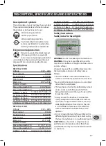
Page 24: ...bly lock x2 12 Rotating blade guard 13 Guard retraction arm 14 Blade bolt cover 15 Dust bag 16 Bevel lock 17 Bevel scale 18 0 Bevel adjuster 19 Fence 19A 19B Fence 20 5mm Hex key 21 Mitre table 22 Mitre scale pointer 23 Table insert kerf plate 24 Switch trigger 25 Mitre lock 25A Locking button 26 Spindle lock 27 Dust extraction port 28 Slide bars 26 29 16 17 19 10 36 23 21 37 36 12 24 5 15 6 3 1 9...

Page 25: ...adjustment screw right 35 0 Bevel adjustment screw 36 Side support bars x2 37 Side support bar location holes 2 sets 38 Side support bar stop screws inside 39 Stabilizer bar 40 Flange wrench 41 Side support bar locking knob x 2 42 Saw blade 43 Ready indicator 44 Working light 8 17 24 12 25 31 36 14 30 28 15 27 39 11 36 10 22 25A 9 44 7 13 19 23 21 B1 16 33 18 34 35 ...

Page 26: ...26 KNOW YOUR PRODUCT B9 4 B3 2 43 B2 30 32 31 B4 B5 B6 B7 B8 EN 42 ...

Page 27: ...intained in ac cordance with the manufacturer s instructions Never aim the beam at any person or an object other than the workpiece The laser beam shall not be deliberately aimed at personnel and shall be prevented from being directed towards the eye of a person for longer than 0 25s Always ensure the laser beam is aimed at a sturdy workpiece without reflective surfaces I e wood or rough coated sur...

Page 28: ... which may get caught in moving parts Nonslip footwear is recom mended Wear protective hair covering to contain long hair 11 Always use safety glasses Also use face or dust mask if cutting operating is dusty Eve ryday eyeglasses only have impact resistant lenses they are NOT safety glasses 12 Secure workpiece Use clamps or a vise to hold workpiece when practical It s safer than using your hand and...

Page 29: ...y c y c s y x c y c cc w R c w c y CAUTION c s c c s y v c c c c y v c c y c w s v s R c c y c s c s s c c WARNING s y x s s s ADDITIONAL SAFETY RULES FOR MITRE SAWS Service T c fi S v c c y fi c s s j y W c s F c c c s z c c s c s c y Additional safety rules for mitre saws c y s y y s w w y s w v s y s s W w v w c s v y v w c w c c c s EN ...

Page 30: ...eces that overhang the turntable Feed workpiece into a blade or cutter against direction of rotation of the blade or cutter only WEAR GOGGLES WEAR EARMUFFS WEAR A BREATHING MASK WARNING For your own safety read instruction manual before operating mitre saw Wear eye protection Keep hands out of path of saw blade Do not operate saw without guards in place Do not perform any operation freehand Never ...

Page 31: ... e epen on cor len an na eplat per rat n tool I t nex av a e Al ay te exte on cor RECOMMENDED SIZES OF EXTENSION CORDS Tool s Ampere rating Volts Total length of cord in feet Cord size in A W G minimum 25ft 50ft 100ft 150ft 3 6 120V 18 16 16 14 6 8 120V 18 16 14 12 8 10 120V 18 16 14 12 10 12 120V 16 16 14 12 12 16 120V 14 12 ADDITIONAL SAFETY RULES FOR MITRE SAWS EN ...

Page 32: ... 8 or outer castings Do not lift the saw using the guard or operating handle 7 Bench mounting The saw base has holes in each corner to facilita te bench mounting 1 Mount the saw to a level horizontal bench or work table and fix the saw to the bench using 4 bolts not supplied 2 f desired you can mount the saw to a piece of 13mm or thicker plywood which can then be clamped to your work support or mov...

Page 33: ...d into the workpiece Dust bag The dust bag 15 fits over the dust extraction the dust bag when it is no more than half full This allows better air flow through the bag Attaching the side bars The side support bars 36 help to support the material when working with long workpieces There are two location holes 37 for a support bar on either side of the table Loosen the stop with a Phillips head screwdri...

Page 34: ...ment screw 35 with a 4mm hex key not supplied to bring the saw blade into alignment with the square 13 Loosen the 2 Phillips head screws holding the pointer of the bevel scale 17 and adjust the position of the pointer so that it accu rately indicates zero on the scale Retighten the screw 14 Retighten the bevel lock 16 and the lock nut securing the 0 bevel adjustment screw 35 NOTE The above procedu...

Page 35: ...il the spindle locks B6 8 Use the flange wrench 40 provided to loosen and remove the blade bolt Loosen in a clockwise direction as the blade screw has a left hand thread B7 9 Remove the flat washer and outer blade washer and the blade B8 10 Wipe a drop of oil onto the inner blade washer and the outer blade washer where they contact the blade 11 Fit the new blade onto the spindle taking care that the...

Page 36: ...w arm 5 to its highest position and slide it towards you 2 Hold the handle firmly and squeeze the switch trigger 24 Allow the blade to reach maximum speed 3 Slowly lower the blade into the workpiece and slide it away from you at the same time until the workpiece is cut 4 Release the switch trigger 24 and allow the saw blade to stop rotating before raising the blade out of the workpiece Wait until t...

Page 37: ...lock 16 6 Place the workpiece flat on the table with one edge securely against the fence 19 If the board is warped place the convex side against the fence If the concave side is placed against the fence the board could break and jam the blade 7 When cutting long pieces of timber support the opposite end of the timber with the side bars 36 a roller stand or a work surface that is level with the saw ...

Page 38: ...ade align the right hand laser line with the pencil mark 5 Plug in the machine and start the motor 6 When the blade is at its maximum speed approximately 2 seconds lower the blade through the workpiece 7 After completing the cut switch off the laser light on off switch 2 8 After each use clean the laser light assembly 1 as described below Switch off the laser light switch 2 and then remove the plu...

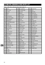
Page 39: ...ate gear Shaft Bearing Flange screw Fix guard Screw Bottom guard Columnar bearing Gear Middle shaft End cap Brush spring Tapping screw Brush Brush holder Hex screw Carring handle B Lock nut Cord armor Cord plug Cord clip Tapping screw Carring handle A Tapping screw Tapping screw Screw Lamp window Operation handle A Lamp assemble Trigger Switch Laser switch Operation handle B Switch knob Tapping sc...

Page 40: ... Lock bolt Mitre Locker Mitre Locker cap Release knob Support bar Attach table L Spring Pin Mitre lock pole Hex screw Link 2 Ring Axis Spring sleeve Big torsion spring Spring washer Trench depth bracket Bracket Deep screw Lock washer Bearing cover Screw Linear bearing Bearing cover Spring loop Arm Knob L Lock nut Big washer Orientation pin Bevel lock bolt Bevel lock handle Hex screw 121 122 123 12...

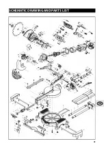
Page 41: ...SCHEMATIC DRAWING AND PARTS LIST EN 41 ...

Page 42: ...ine at 1 866 206 0888 from 8 AM to 6 PM Monday to Friday Eastern time RONA reserves the right to repair or replace the defective tool at its discretion Normal wear and tear including accessory wear is not covered under guarantee The product is guaranteed for 36 months if used for normal trade purposes Any guarantee is invalid if the product has been overloaded or subject to neglect improper use or...

Page 43: ...34 ...

Reviews: