background image

26

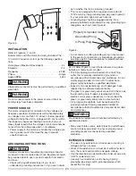
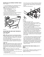
RAISING AND LOWERING THE FEED TABLE

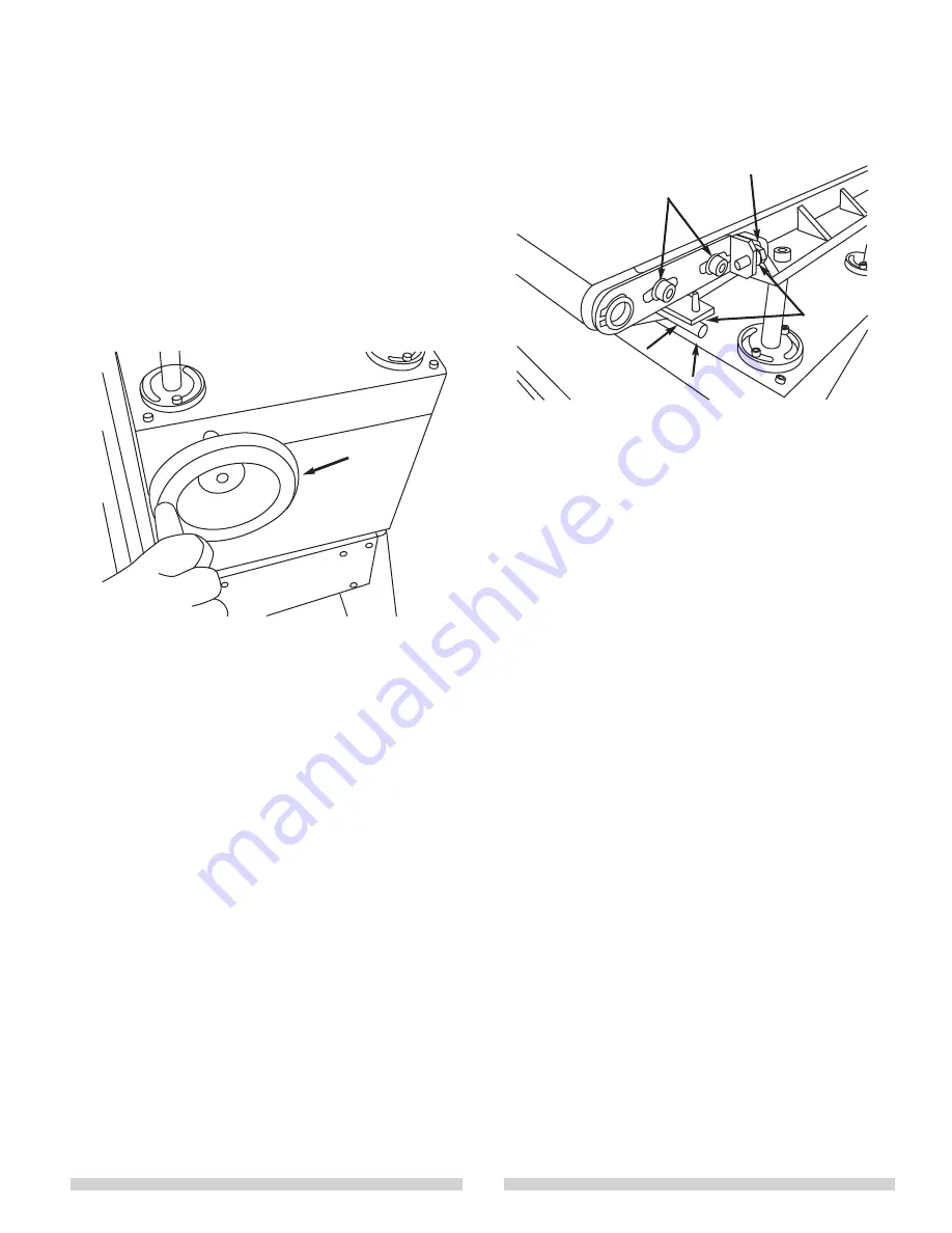
Refer to Figure 11.

•   To raise the feed table, turn the handwheel clockwise.   
   To lower, turn handwheel counter-clockwise.

NOTE:

 Each turn of the handwheel will increase or 

decrease the height of the table by 1/16”.
•   Stock removed settings:
   1/4 turn - For material removal (1/64”)
   1/8 turn - For general finishing (1/128”)
   1/16 turn - For fine finishing passes
On the last finishing passes, pass the board through two 
or three times to level hard spots or knots.
• Reduce depth of stock removal for wider boards and 
hardwoods to prevent tripping overload protection.

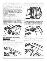
ADJUSTING TRACKING AND TENSION ON

THE FEED BELT

Refer to Figure 12.

NOTE: 

With a new belt, it is not unusual for one side of 

the belt to be tighter than the other to make the belt track.
Frequent adjustments are normal for the first few hours of 
use to allow for belt stretch. Adjustments to belt tracking 
can also affect belt tension.
Belt should ride centered on the drive and idler rollers. 
The drum sander is shipped with the tracking and tension 
properly adjusted. However, if adjustment is necessary:

Tensioning

NOTE:

 When adjusting belt tension, tighten or loosen both

bolts the same amount to avoid affecting belt tracking. DO
NOT over-tension the belt. Excessive tension will cause 
premature wear of belt, bearings and overload the motor. 
Listen for motor load speed changes when adjusting belt 
tension.

NOTE:

 Adjustments to belt tension can affect belt 

tracking. Frequent adjustments are normal for the first few 
hours use to allow for belt stretch.
•   The belt needs adjustment if it slips on the rollers during
   sanding operations.
•   Loosen all four socket head bolts (A).

•   Loosen hex nut. Turn both hex head bolts (B) clockwise  
   1/4 turn and check tension. Repeat until the feed belt is  
   tensioned properly. Tighten hex nuts to secure bolts in   
   position.
•   Tighten all socket head bolts.

Tracking

•   Connect tool to power source.
•   Turn belt feed speed control knob to the maximum  


   speed, and run the feed table several minutes to check  
   for proper tracking of the feed belt.
•   Let the belt run and observe tracking direction. If belt    
   does not move to either side within five minutes of  


   running, no adjustment is needed.
•   To correct improper tracking of the feed belt to the left,
   loosen the hex nut of the tracking bar assembly and turn
   the socket head bolt (on the left side of the table)  


   counterclockwise 1/4 turn. (Counterclockwise direction  
   as viewed from the head of the bolt.) Continue this  


   adjustment until the feed belt is tracking properly on the  
   feed rollers. Let the feed belt run several minutes before  
   adjusting again. Tighten the hex nut to secure tracking  
    bar in position.

•   To correct improper tracking of the feed belt to the right,
   loosen the hex head nut of the tracking bar assembly    
   and turn the socket head bolt (on the right side of the    
   table) counterclockwise 1/4 turn. (Counterclockwise    
   direction as viewed from the head of the bolt.) Continue  
   this adjustment until the feed belt is tracking properly on  
   the feed rollers. Let the feed belt run several minutes    
   before adjusting again. Tighten the hex nut to secure    
   tracking bar position.

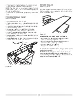
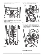
ADJUSTING FEED TABLE PARALLEL TO 

DRUM

Refer to Figure 13.

The drum sander is shipped from the factory with the drum
carriage set parallel to the feed table. However, if 
adjustment is necessary:

Volant

Figure 11 - 

A

B

Hex Nut

Tracking

Bar

C

Figure 12 - 

Summary of Contents for 5848003

Page 1: ...illez appeler notre numéro sans frais 1 866 599 5916 poste 2 Our Customer Service staff are ready to provide assistance In the case of a damaged or missing part most replacement parts ship from our facility in two business days For immediate help with assembly or for additional product information call our toll free number 1 866 599 5916 ext 2 CONSERVEZ CE GUIDE Vous aurez besoin de ce guide pour ...

Page 2: ...sques ou des respirateurs approuvés OSHA NIOSH qui s ajustent correctement lors de l utilisation de ces outils CONSIGNES DE SÉCURITÉ AVERTISSEMENT CARACTÉRISTIQUES DU PRODUIT AVERTISSEMENT Pour des raisons de sécurité personnelle lire l ensemble des instructions et des précautions à prendre avant d utiliser l outil AVERTISSEMENT Toujours respecter les marches à suivre décrites dans ce manuel même ...

Page 3: ...les outils et les clés de réglage sont retirés de l outil avant de le mettre en marche Garder toutes les pièces en bon état de fonctionnement S assurer que le protecteur et toutes les autres pièces fonctionnent adéquatement et qu elles remplissent les fonctions pour lesquelles elles sont prévues S assurer qu aucune pièce n est endommagée S assurer que les pièces mobiles sont bien alignées qu elles...

Page 4: ...muniquer avec le détaillant ou téléphoner au 1 866 599 5916 poste 2 La ponceuse à tambour est livrée complètement assemblée Les pièces à monter sur la ponceuse à tambour doivent être repérées et il faut s assurer qu il n en manque aucune avant de les monter A Pied 4 B Petit support 2 C Petite traverse 2 D Grande traverse 2 E Grand support 2 F Goulotte G Volant H Collecteur de poussière I Sac de qu...

Page 5: ...PORT Se reporter à la Figure 2 ATTENTION La ponceuse à tambour est lourde Cette opération exige deux personnes Placer la ponceuse à tambour sur le support S assurer que les trous sur le dessus des supports du support sont alignés avec les trous situés au bas de la base du support Bloquer en place à l aide de boulons à tête hexagonale de rondelles plates et d écrous hexago naux FIXATION DU VOLANT À...

Page 6: ...à trois conducteurs approuvé pour être branché sur le courant alternatif de 120 volts et d une fiche à 3 broches avec terre pour une tension nominale de 125 volts Figure 6 pour protéger l utilisateur contre les risques de chocs électriques La fiche de mise à la terre doit être branchée directement dans une prise de courant à 3 bornes avec terre montée correctement tel qu il est illustré Figure 6 N...

Page 7: ...ns électriques doivent être effectuées par un électricien qualifié S assurer que l outil est arrêté et débranché de la source d alimentation pendant le montage le branchement du moteur ou lors de l inspection du câblage Le moteur et les câbles sont installés tel qu il est illustré sur le schéma de câblage voir la Figure 8 Le moteur est assemblé avec un cordon à trois conducteurs approuvé pour util...

Page 8: ...s porter une protection oculaire ou un écran facial S assurer que la courroie d entraînement s aligne correctement Un alignement correct permet d obtenir le meilleur résultat Après avoir mis l appareil en marche laisser le tambour atteindre son plein régime avant de poncer Dégager la table de travail de tout objet outils morceaux de bois etc avant de démarrer l outil Garder les mains à bonne dista...

Page 9: ...ilisée Enlever la clé et la garder en lieu sûr En cas de panne de courant d un fusible grillé ou d un disjoncteur déclenché placer l interrupteur à la position d arrêt OFF et enlever la clé afin d éviter une mise en marche accidentelle lors du rétablissement du courant RELEVAGE ET ABAISSEMENT DE LA TABLE D AVANCE Se reporter à la Figure 11 Pour relever la table d avance tourner le volant dans le s...

Page 10: ... réglage n est requis Pour corriger un alignement incorrect de la courroie d entraînement vers la gauche desserrer l écrou hexagonal de la barre d alignement et tourner le boulon à tête creuse sur le côté gauche de la table de 1 4 tour dans le sens antihoraire Sens antihoraire tel que vu à partir de la tête du boulon Continuer le réglage jusqu à ce que la courroie d entraînement s aligne correctem...

Page 11: ...ire tourner le tambour à la main pour retirer la courroie Dégager la courroie de la bride à l autre extrémité du tambour voir la Figure 15 Pour remplacer la courroie abrasive placer son extrémité rebord conique à l extérieur du tambour entre la bride et le tambour fixer en position en serrant le boulon à tête creuse et enrouler la courroie en faisant tourner le tambour à la main voir la Figure 16 ...

Page 12: ...anuel ROULEAU DE RETOUR Se reporter à la Figure 19 La ponceuse à tambour est munie d un rouleau de retour situé sur le couvercle du tambour ce rouleau permet de déplacer facilement la pièce vers l avant de la ponceuse pour effectuer une autre passe APPLICATIONS POUR LE TYPE DE GRAIN DE LA COURROIE DE PONÇAGE Abrasif 60 grains Utilisé pour poncer les matériaux bruts et les surfaces rugueuses de mêm...

Page 13: ...L Si le cordon d alimentation est usé coupé ou endommagé le faire remplacer immédiatement Remplacer les abrasifs usés selon le besoin Remplacer toute pièce endommagée ou manquante Utiliser la liste des pièces ci jointe pour commander des pièces Toute tentative de réparation du moteur peut entraîner un risque à moins d être effectuée par un technicien de service qualifié Pour plus de renseignements...

Page 14: ...ever le support du moteur afin de retirer et remplacer la courroie d entraînement voir la Figure 24 Pour retirer et remplacer la courroie à vitesse variable la poulie extérieure d entraînement de vitesse variable doit être enlevée Desserrer et retirer la rondelle du boulon à tête creuse et la poulie voir la Figure 25 Réassembler dans l ordre inverse Figure 23 Figure 24 Figure 25 Courroie d entraîn...

Page 15: ...ou par d autres moteurs 2 Fils de calibre trop petit ou circuits trop longs 3 Surcharge générale des installa tions du fournisseur d électricité 1 Réduire la charge sur la ligne d alimentation 2 Augmenter le calibre des fils ou réduire leur longueur 3 Demander au fournisseur d électricité de vérifier la tension Le moteur cale ce qui grille les fusibles ou déclenche le disjoncteur 1 Surcharge moteu...

Page 16: ...15 ...

Page 17: ...billes 6003zz 1 67 180430 Axe 1 68 Roulement à billes 6002zz 1 69 STD870525 Boulon à tête creuse de 5 0 8 x 25 mm 2 70 Rondelle frein de 5mm 2 71 180550 Cheville 1 72 180530 Tige 1 73 Vis M6 X 6L 1 74 180540 Support 1 75 180560 Tige 1 76 Écrou M5 2 77 180620 Arrêt 2 78 181061 Écrou 1 79 181524 Chaîne 132 410 1 80 180151 Capuchon anti poussière 1 81 Vis à tête cylindrique bombée 5 0 8 x 10 mm 1 82 ...

Page 18: ... 209 STD870625 Vis à tête cylindrique bombéede 6 1 0 x 25 mm 1 210 181536 Serre câble 1 211 180130 Support de roulement 1 212 Roulement à billes 6005zz 1 213 Anneau de retenue 3AMI 25 2 214 181040 Cordon électrique 14WG X3C 105 1 215 STD870625 Boulon à tête creuse de 6 1 0 x 25mm 2 216 180300 Butée plaqued arrêt 2 217 180791 Ressort 2 218 180280 Rondelle plate 1 219 180470 Couvercle 1 220 180490 A...

Page 19: ...i de 8h à 18 h heure normale de l Est RONA se réserve le droit de réparer ou remplacer l outil défectueux à sa discrétion L usure normale incluant l usure des accessoires n est pas couverte par cette garantie Ce produit est garanti durant 36 mois si utilisé de façon normale Toute garantie est invalide si le produit a été utilisé en surcharge ou de façon non recommandée ou a fait l objet de néglige...

Page 20: ...ICATIONS For your own safety read all of the rules and precautions before operating tool Always follow proper operating procedures as defined in this manual even if you are familiar with use of this or similar tools Remember that being careless for even a fraction of a second can result in severe personal injury 19 WARNING WARNING Safety Rules 21 Preparation 22 Assembly 23 Operation 27 Maintenance...

Page 21: ... to see that adjusting tools or accessories are removed before switching tool on Keep all parts in working order Check to determine that guard or other parts will operate properly and perform their intended function Check for damaged parts Check for alignment of moving parts binding breakage mounting and any other condition that may affect tool s operation A guard or any other part that is damaged...

Page 22: ...ing is missing or broken contact the RONA Customer Service at 1 866 599 5916 ext 2 The drum sander comes assembled as one unit Additional parts which need to be fastened to the drum sander should be located and accounted for before assembling A Leg 4 B Small Support 2 C Small Brace 2 D Large Brace 2 E Large Support 2 F Dust Chute G Handwheel H Dust Collection Set I Hardware Bag 21 A B E F C G H I ...

Page 23: ...floor and tighten all bolts and nuts firmly MOUNT DRUM SANDER TO STAND Refer to Figure 2 CAUTION The drum sander is heavy Two people will be required to perform this operation Place drum sander onto stand Make sure that holes on top of the stand supports are aligned with holes in bottom of the bed of drum sander Secure in position using hex head bolts flat washers and hex nuts ATTACH HANDWHEEL TO ...

Page 24: ...see Figure 6 Do not remove or alter grounding prong in any manner In the event of a malfunction or breakdown grounding provides a path of least resistance for electrical shock Do not allow fingers to touch the terminals of plug when installing or removing from outlet The 3 prong plug must be inserted into a matching outlet that is properly installed and grounded in accordance with all local codes ...

Page 25: ...uctor cord to be used at 115 volts Motor is prewired at the factory for 115 volts Drum Sander has a locking rocker switch with removable key for safe and easy operation Remove the key from the locking rocker switch to prevent unauthorized use of the tool To replace the key press key into the slot on the locking rocker switch Drum sander also has a manual reset overload protector to prevent damage ...

Page 26: ...ed Do not force the work into the abrasive Support long or wide workpieces with a roller stand at table height Never push a sharp corner of the workpiece rapidly against belt Abrasive backing may tear Replace abrasives when they become loaded glazed or frayed Check belts for tightness This tool is designed to sand wood or wood products only Do not attempt to sand metal on this tool Do not sand pie...

Page 27: ... the rollers during sanding operations Loosen all four socket head bolts A Loosen hex nut Turn both hex head bolts B clockwise 1 4 turn and check tension Repeat until the feed belt is tensioned properly Tighten hex nuts to secure bolts in position Tighten all socket head bolts Tracking Connect tool to power source Turn belt feed speed control knob to the maximum speed and run the feed table severa...

Page 28: ...e a few thousandths of an inch higher to allow sanding a crown rather than a groove Sand the board again to check adjustment readjust if necessary Tighten socket head bolts DRUM SANDING BELT REPLACEMENT Disconnect tool from power source The drum sanding belt is held on the drum with a spring loaded clamp located on each side of the drum To remove the sanding belt loosen the socket head bolt and ra...

Page 29: ...ning the socket head bolts on the elevating screws Adjust tension and tracking refer to Adjusting Tracking and Tension of Feed Belt in the manual RETURN ROLLER Refer to Figure 19 The drum sander has a return roller on the drum cover so that the workpiece can be easily moved to the front of the sander for another pass SANDING BELT GRIT APPLICATIONS 60 grit Used for heavy stock removal and rough sur...

Page 30: ...lly oil bushings on the pressure rollers and feed table rollers TOOL REPAIRS If power cord is worn cut or damaged in any way have it replaced immediately Replace worn abrasive when needed Replace any damaged or missing parts Use parts list to order parts Any attempt to repair motor may create a hazard unless repair is done by a qualified service technician For further information about repairs ple...

Page 31: ...e 23 Use a pry bar to lift motor bracket to remove and replace the feed drive belt See Figure 24 To remove and replace the variable speed belt the outer variable speed drive pulley must be removed Loosen and remove the socket head bolt washer and pulley See Figure 25 Reassemble in reverse order Boulons à tête creuse Support de roulement Figure 22 Drum Drive Belt Idler Assembly Socket Head Bolt Soc...

Page 32: ...ights appliances and other motors 2 Undersize wires or circuits too long 3 General overloading of power company s facilities 1 Reduce the load on the power line 2 Increase wire sizes or reduce length of wiring 3 Request a voltage check from the power company Motor stalls resulting in blown fuses or tripped cir cuit breakers 1 Motor overload too much stock removed per pass 2 Short circuit in motor ...

Page 33: ...32 NOTES ...

Page 34: ...33 ...

Page 35: ...NG 6002zz 1 69 STD870525 HEX SOC HD SCR M5X25L 2 70 SPRING WASHER M5 2 71 180550 PIN 1 72 180530 LINK 1 73 SET SCREW M6X6L 1 74 180540 BRACKET 1 75 180560 ADJUSTING ROD 1 76 HEX NUT M5 2 77 180620 RETAINER 2 78 181061 NUT 1 79 181524 CHAIN 1 80 180151 DUST COVER 1 81 CROSS PAN HEAD SCREW M5X10L 1 82 FLAT WASHER 1 83 180950 KNOB 1 84 181525 SWITCH 1 85 181526 SWITCH RESET 1 86 181050 SPEED SCALE 1 ...

Page 36: ...G 1 209 STD870625 CROSS PAN HEAD SCREW M6X25L 1 210 181536 STRAIN RELIEF 1 211 180130 BEARING HOUSING 1 212 BEARING 6205ZZ 1 213 EXT RET RING STW25 2 214 181040 POWER CORD 1 215 STD870625 HEX SOC HD SCR M6X25L 2 216 180300 LOCKING BLOCK 2 217 180791 SPRING 2 218 180280 FIXED PAN 1 219 180470 FIXED PAN 1 220 180490 HEAD SHAFT 1 221 KEY 2 222 180440 DRUM 1 223 180900 ABRASIVE BELT 80 GRIT 1 224 1804...

Page 37: ... 866 599 5916 Ext 2 from 8 AM to 6 PM Monday to Friday Eastern time RONA reserves the right to repair or replace the defective tool at its discretion Normal wear and tear including accessory wear is not covered under guarantee The product is guaranteed for 36 months if used for normal trade purposes Any guarantee is invalid if the product has been overloaded or subject to neglect improper use or a...

Page 38: ...37 ...

Reviews: