background image

23

4001012670

E 06.20 

 USA / GB

Compact 8 (C 2032E) - Compact 8W (C 2047E) - Compact 10 (C 2747E) - Compact 10N 
(C 2632E) - Compact 10N-1 - Compact 12 (C 3347E) - Compact 14 (C 3947E)

C - 

Familiarization

 1.3 - 

MANUAL


EXTENSION

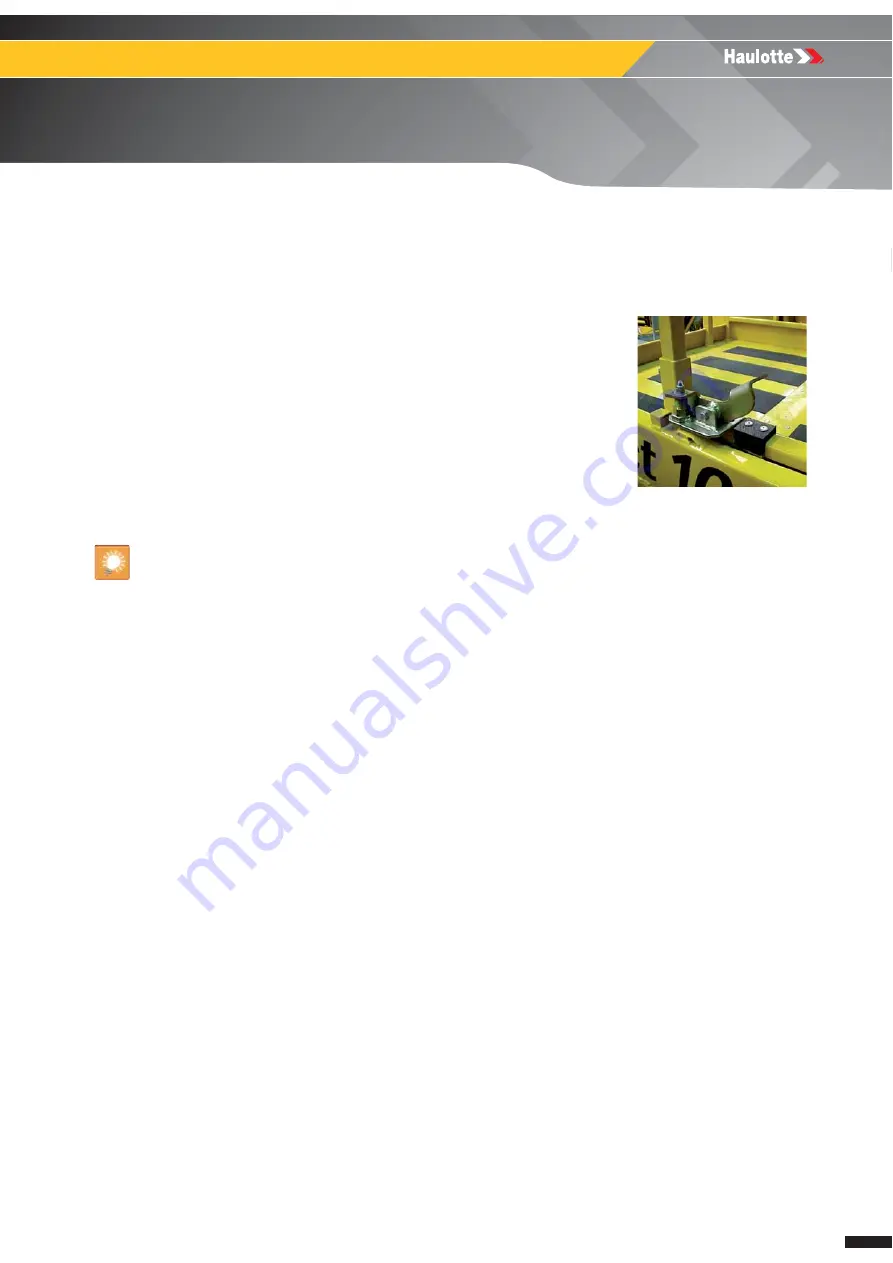
Machines are equipped with manual extension with several possible positions. 

For :  C8 (COMPACT 2032E) - C8W (COMPACT 2047E) - C10N (COMPACT 2632E) - C10
(COMPACT 2747E) - C12 (COMPACT 3347E) - C14 (COMPACT 3947E)

N.B.-:-D

O


NOT


LOAD


THE


EXTENSION


DECK

FOR


EASE


OF


MANOEUVRING

• Press the pedal. 

•  Push to the required notch. 

The extension deck must be retracted and locked during transport or towing. 

Summary of Contents for COMPACT 10

Page 1: ... OMPACT 10N C 2632E C OMPACT 10N 1 C OMPACT 12 C 3347E C OMPACT 14 C 3947E 4001012670 E 06 20 USA GB MAINTENANCE BOOK Compact 8 Compact 2032E Compact 8W Compact 2047E Compact 10 Compact 2747E Compact10N Compact2632E Compact10N 1 Compact 12 Compact 3347E Compact 14 Compact 3947E ...

Page 2: ...2 4001012670 E 06 20 USA GB Compact 8 C 2032E Compact 8W C 2047E Compact 10 C 2747E Compact 10N C 2632E Compact 10N 1 Compact 12 C 3347E Compact 14 C 3947E 24203 0USA ...

Page 3: ... 1 2 Uncontrolled movement Hazard 12 1 3 Electric Shock Hazards 13 1 4 Explosion Fire Hazards 14 2 Maintenance and repair training 15 2 1 Owner s responsability 15 2 2 Technician s responsability 15 2 3 HAULOTTE Services 15 2 4 Training 15 2 5 Product modification 16 2 6 After Sales Service 16 2 7 Product information 16 3 Conditions of warranty 17 ...

Page 4: ...nual extension 23 1 4 Ground control box 24 1 4 1 Layout 24 1 5 Platform control box 26 1 5 1 Layout 26 2 List of actuators and sensors 28 2 1 Sensors and actuators 28 2 2 Sensors detail 29 3 Consumables 31 4 Ingredient 31 4 1 Hydraulic oil 31 5 Lubrication diagram 32 6 Machine specifications 34 6 1 Movement speed 34 ...

Page 5: ...t inspection 43 E001 Oil tank 47 MS0002 Pins and bearing inspection 49 MS0003 Cylinder inspection 53 E003 Hydraulic filter cartridge 57 MS0004 Braking test procedure 59 MS0005 Torque Values 61 E006 Wheel 65 E010 Steering wheel pivots 71 E011 Guide rail 73 E012 Cylinder hinge 75 MS0020 Hoses inspection Replacement 77 MS0025 Electrical wiring 81 E049 Jib cylinder Steering cylinder Lift cylinder 83 M...

Page 6: ...t pinning 94 2 1 2 Serial card 96 2 2 Electric circuit 97 2 2 1 Main components 97 2 2 2 Fuses 98 2 2 3 Relays and terminals 98 2 2 4 Switches 99 2 2 5 Buzzers 99 2 2 6 Indicators 99 2 3 Hydraulic circuit 100 2 3 1 Main components 100 2 3 2 Hydraulic units 102 2 3 2 1 Details of MK5 hydraulic unit 102 2 3 2 2 Details of MK6 hydraulic unit 104 3 Electric diagram 106 4 Hydraulic diagram 110 F RECORD...

Page 7: ...ts Compliance with safety instruction machine use environment Use of the equipment within the performance limits With regard to the designation of our equipment we stress that this is purely for commercial purposes and not to be confused with the technical specifications Only the specifications in this manual should be used to study the suitability of the equipment for the intended use This mainte...

Page 8: ...oughout this manual to indicate specific hazards and the hazard severity level when operating or maintaining the Aerial Work Platform Symbol Symbol Description Danger Risk of injury or death Caution Risk of material damage Prohibition relating to work safety and quality Reminder to use good practice or follow pre operation checks Cross reference to another part of the manual Cross reference to ano...

Page 9: ...ATE SPECIFIC HAZARDS WHEN OPERATING OR MAINTAINING THE TELEHANDLER Color Title Description Danger Indicates a hazardous situation which if not avoided WILL result in death or serious injury Warning Indicates a hazardous situation which if not avoided COULD result in death or serious injury Caution Failure to comply could result in minor or moderate injury Notice Indicates practices not related to ...

Page 10: ...10 4001012670 E 06 20 USA GB Compact 8 C 2032E Compact 8W C 2047E Compact 10 C 2747E Compact 10N C 2632E Compact 10N 1 Compact 12 C 3347E Compact 14 C 3947E A Preface Foreword Notes ...

Page 11: ...configuration The maintenance stand must be in place before any maintenance operation is begun Never leave the hydraulic cylinders fully extended before switching off the machine or when stationary for an extended period of time Keep the elements of the machine in configuration of maintenance thanks to mechanics devices Report that the machine is under maintenance by tagging the platform and groun...

Page 12: ...of uncontrolled movement and always respect the following Maintain clearance from high voltage lines Maintain clearance from generators radar electromagnetic fields Never expose the batteries or electrical components to water high pressure washer rain Never tow the machine over extended distances In case of a machine breakdown it is possible to tow short distance to load it onto a trailer Never le...

Page 13: ...not operate the machine Do not operate the machine when close to live power lines consider the movement of the machine and the sway of the electric power lines particularly in windy conditions Do not operate the machine during lightning thunderstorms snow ice or any weather condition that could compromise operator safety Do not operate the machine during lightning or storms Do not use the machine ...

Page 14: ...AZARDS Always wear protective clothing and eye wear when working with batteries and power sources systems N B ACID IS NEUTRALIZED WITH SODIUM BICARBONATE AND WATER Do not work in an explosive or flammable atmosphere environment Do not touch hot components Do not bridge the battery terminals with metallic objects Do not service the battery in proximity of spark open flame lit cigarettes ...

Page 15: ...derstand the contents of this manual operators manuals and the decals affixed on the machine The technician must inform the owner or hirer if the manual or any decals are missing or in poor condition and of any malfunction of the machine 2 3 HAULOTTE SERVICES The HAULOTTE is at your service in all 5 continents of the world via an extensive network of its own factory trained technicians who are rea...

Page 16: ...cting our After Sales Service ensure that you provide the machine model and serial number When ordering any consumables or spare parts please use this manual and the HAULOTTE Essential catalogue to receive your genuine HAULOTTE spare parts your only guarantee of parts interchangeability and correct machine operation If there is an equipment malfunction involving a HAULOTTE product then contact HAU...

Page 17: ... 8W C 2047E Compact 10 C 2747E Compact 10N C 2632E Compact 10N 1 Compact 12 C 3347E Compact 14 C 3947E B Safety 3 Conditions of warranty Our warranty conditions and extension contracts are now available on the websites of our sales network www haulotte com ...

Page 18: ...18 4001012670 E 06 20 USA GB Compact 8 C 2032E Compact 8W C 2047E Compact 10 C 2747E Compact 10N C 2632E Compact 10N 1 Compact 12 C 3347E Compact 14 C 3947E B Safety Notes ...

Page 19: ...19 4001012670 E 06 20 USA GB Compact 8 C 2032E Compact 8W C 2047E Compact 10 C 2747E Compact 10N C 2632E Compact 10N 1 Compact 12 C 3347E Compact 14 C 3947E C Familiarization Familiarization Notes ...

Page 20: ...2 C 3347E Compact 14 C 3947E C Familiarization 1 Primary machine components 1 1 LAYOUT COMPACT 8 COMPACT 2032E COMPACT 8W COMPACT 2047E COMPACT 10N COMPACT 2632E COMPACT 10 COMPACT 2747E COMPACT 12 COMPACT 3347E COMPACT 14 COMPACT 3947E C87 C87 C20 C1 C6 C35 C75 C7 C42 C68 C76 C2 C142 C77 C59 C27 C88 C143 C142 C30 C58 C141 C154 ...

Page 21: ... midrail C2 Front driven steering axle C68 Electric socket Option C6 Platform C75 Extension C7 Platform control box C76 Guardrail C20 Tie down and or lifting points C77 Platform access ladder C27 Ground control box Universal plug C87 Position of the lift truck forks C30 Hydraulic oil tank C88 Battery drawer lock C35 Document holder C141 Rear wheel C42 Foot Switch For Japan only C142 Machine anchor...

Page 22: ...height to tilt the stand Unscrew rotate and put the stand in the vertical position The stand should remain in the vertical position Lower the scissor arms Scissor arm pivoting rod should rest on the V groove of the stand Putting in use position To put back the machine into its normal operation reverse the steps used above COMPACT 8 C 2032E COMPACT 8W C 2047E COMPACT 10 C 2747E COMPACT 10N C 2632E ...

Page 23: ...MANUAL EXTENSION Machines are equipped with manual extension with several possible positions For C8 COMPACT 2032E C8W COMPACT 2047E C10N COMPACT 2632E C10 COMPACT 2747E C12 COMPACT 3347E C14 COMPACT 3947E N B DO NOT LOAD THE EXTENSION DECK FOR EASE OF MANOEUVRING Press the pedal Push to the required notch The extension deck must be retracted and locked during transport or towing ...

Page 24: ...10N 1 Compact 12 C 3347E Compact 14 C 3947E C Familiarization 1 4 GROUND CONTROL BOX 1 4 1 Layout General view COMPACT 8 COMPACT 2032E COMPACT 8W COMPACT 2047E COMPACT 10 COMPACT 2747E COMPACT 10N Compact 2632E COMPACT 10N 1 COMPACT 12 COMPACT 3347E COMPACT 14 COMPACT 3947E E stop button 92 6 106 105 107 91 93 144 ...

Page 25: ...e left Platform control box energized Center De energizes control system Move downwards Move to the right Ground control box energized 93 Battery charging indicator Battery charge level status during battery charging 105 Flashing light selector Move upwards Switching on the flashing light Move downwards Switching off the flashing light 106 Platform raising lowering selector Move upwards Platform r...

Page 26: ...0N C 2632E Compact 10N 1 Compact 12 C 3347E Compact 14 C 3947E C Familiarization 1 5 PLATFORM CONTROL BOX 1 5 1 Layout General view COMPACT 8 COMPACT 2032E COMPACT 8W COMPACT 2047E COMPACT 10 COMPACT 2747E COMPACT 10N COMPACT 2632E COMPACT 10N 1 COMPACT 12 COMPACT 3347E COMPACT 14 COMPACT 3947E ...

Page 27: ...ck Move forward Forward drive or platform raising Move backwards Reverse drive or platform lowering Front axle steering selector Press right side of button Right hand steering Press left side of button Left hand steering 110 Elevation Lowering selection indicator On Raising Lowering selection activated Off Raising Lowering movement is not selected 111 Driving selection indicator On Driving functio...

Page 28: ... and sensors 2 1 SENSORS AND ACTUATORS Sensors and actuators Marking Description A1 Angle sensor C12 Platform lowered after the 3m cut out G1 Pressure sensor weighing SP1 Overload pressure switch SQ1 Low position switch SQ3 High position switch SQ5 Left pothole position limit switch SQ6 Right pothole position limit switch SQ7 Manual extension contactor Weighing only option SQ10 Tilt contactor ...

Page 29: ...ompact 12 C 3347E Compact 14 C 3947E C Familiarization 2 2 SENSORS DETAIL Marking Item Description 1 A1 Relative angle sensor 2 G1 Pressure sensor weighing 3 SQ1 Low stop detection 4 SQ3 High detection 32 0 If platform with maximum height 5 SQ5 Left pothole position limit switch 6 SQ6 Right pothole position limit switch ...

Page 30: ...0N 1 Compact 12 C 3347E Compact 14 C 3947E C Familiarization Marking Item Description 1 C12 SQ4 Platform lowered after the 3m cut out 2 SP1 Overload pressure controller 28 If strain gauge not mounted 3 SQ1 Low stop detection 29 1 if PF 3 m 4 SQ7 Manual extension contactor Weighing only option 5 SQ10 Slope detection ...

Page 31: ...they comply with the following requirements Ambient operating temperature between 15 C 9 F and 40 C 104 F HEES type biodegradable oil only according to standards ISO 15380 and VDMA 24568 Necessary characteristics Consumable HAULOTTE code Hydraulic filter cartridge 2427002940 Ingredient HAULOTTE code Hydraulic oil 2420801310 Hydraulic oil Winter option 2505002640 Biological hydraulic oil 2820304310...

Page 32: ...4001012670 E 06 20 USA GB Compact 8 C 2032E Compact 8W C 2047E Compact 10 C 2747E Compact 10N C 2632E Compact 10N 1 Compact 12 C 3347E Compact 14 C 3947E C Familiarization 5 Lubrication diagram 5 4 3 6 5 6 ...

Page 33: ...on List of ingredients Marking Ingredient Symbol HAULOTTE code 3 Hydraulic oil Standard Barrel 209 l 55 2 gal US 2420801310 Hydraulic oil Winter option 2505002640 4 Biological hydraulic oil Barrel 209 l 55 2 gal US 2820304310 5 Extreme pressure lithium grease 2820304320 6 Lead free grease Aerosol 0 4 l 0 1 gal US 2820304330 Lead free grease Can 5 l 1 32 gal US 2820304340 ...

Page 34: ...peed during towed operation 1 km h 0 62 mph Time for lifting at maximum height 26 s 5 s 34 s 5 s Time for lowering to minimum height 41 s 5 s 47 s 5 s COMPACT 10 COMPACT 2747E COMPACT 10N COMPACT 2632E Micro drive speed 0 8 km h 0 50 mph Low drive speed 1 5 km h 0 93 mph High drive speed 3 km h 1 86 mph Maximum freewheel speed during towed operation 1 km h 0 62 mph Time for lifting at maximum heig...

Page 35: ...t be performed every day before the start of a new work shift and at every change of user This inspection is performed by and under the responsibility of the user and includes the visual and functional inspection of the machine as well as the testing of its safety systems A description of the daily inspection can be found in the machine s user manual We recommend these forms to be completed daily ...

Page 36: ...e recorded in a register log book of the machine Symbol meanings Preventive Maintenance Level 1 First 50H The information contained in our manual is to be complemented by the information found in the engine manufacturer s maintenance manual which can be found on the link in the associated maintenance sheet MS0238 Oil change To check by test Tightening Levelling Visual inspection Functional adjustm...

Page 37: ...Every 2 weeks OK NOK Corrected Comments Batteries Check the electrolyte level of the battery batteries E018 Every 6 months or 250H Page or associated procedure Every 6 months or 250H OK NOK Corrected Comments Chassis assembly Wheel reducer steering wheel pivot Tighten the wheel nuts Grease the steering system Clean the pads slide Check that the ground strap is present and in good condition Hydraul...

Page 38: ...iated procedure Every 1 year or 500H OK NOK Corrected Comments Batteries Check the condition of the battery terminals cables Corrosion not damaged Grease the terminals Hydraulic oils filters and hoses Replace the hydraulic filter Every 2 years or 1000H Page or associated procedure 2 year s or 1000H OK NOK Corrected Comments Chassis assembly Wheel reducer steering wheel pivot Check the bushings and...

Page 39: ...onents Any accident causing stress to the machine This inspection is the responsibility of the owner and must be conducted by a qualified technician Under no circumstances may this inspection replace the control required by local regulations Use the detailed program below Periodic Page or associated procedure Periodic OK NOK Corrected Comments Chassis assembly Wheel reducer steering wheel pivot Ch...

Page 40: ...nts Check for the absence of visible deterioration and damage Check for the absence of cracks broken welds and chipped paintwork on the structure Check for the absence of missing or loose screws and bolts Check for the absence of deformation cracking and breakage of axis stops bushing and axes Check for the absence of foreign bodies in joints and sliding parts Safety devices Test the operation of ...

Page 41: ...chine to ensure that it is fully functional It must be carried out after 10 years then every 5 years This inspection is the responsibility of the owner and must be carried out by a technician HAULOTTE Services or an authorized and qualified person In order to carry it out contact the subsidiary HAULOTTE or the authorized distributor Machine sheet N B THE LIST OF MAINTENANCE SHEETS IS NOT EXHAUSTIV...

Page 42: ...42 4001012670 E 06 20 USA GB Compact 8 C 2032E Compact 8W C 2047E Compact 10 C 2747E Compact 10N C 2632E Compact 10N 1 Compact 12 C 3347E Compact 14 C 3947E D Inspection and maintenance schedule Notes ...

Page 43: ...s familiar with all of the safety information contained in the user manual Generally speaking the user must comply with regulatory obligations in force particularly those relating specifically to working alone co activity and manual load handling The user must have all the permits authorizations required to work fire permit etc and comply with the specific safety instructions at the intervention s...

Page 44: ...ction If anomalies are noted according to the list below a reinforced control will have to be carried out to judge conformity of the part Absence of foreign body to the articulations and slides Absence of deformation and visible damage Absence of crack broken welding oxidation glare of painting Absence of excessive gap to the articulations and slides Check that locking device are not damaged and a...

Page 45: ...The main items to be inspected are Boss welds on chassis turret arms booms and jib Booms and arms welds Example In the event of suspicion of crack a cleaning and a sweating are to be carried out to guarantee the integrity of the part before reassembly Check presence and torque of each bolts and screw used to assembly part listed in Section Familiarization Refer to spare part catalog for additional...

Page 46: ... all the movements without jolts while supporting the load All the security device function correctly Authorized maximum speeds of operation are not exceeded Refer to the user manual for the description of the safety device and technical characteristics to be reached 4 5 STRUCTURAL TEST The following test shows that the structure of the machine is in conformity with the safety requirements The mac...

Page 47: ...PACT 10 COMPACT 2747E COMPACT 12 COMPACT 3347E COMPACT 14 COMPACT 3947E 5 Additional operation 1 Place the machine in its operating configuration 3 3 2 Placing in operating configuration Standard tool kit Protective goggles Gloves Place barriers around the perimeter of the work area Check the oil level when cold before beginning a new period of work Check that the oil level is between the indicate...

Page 48: ...48 4001012670 E 06 20 USA GB Control Filling up Oil tank M001 Notes ...

Page 49: ...is familiar with all of the safety information contained in the user manual Generally speaking the user must comply with regulatory obligations in force particularly those relating specifically to working alone co activity and manual load handling The user must have all the permits authorizations required to work fire permit etc and comply with the specific safety instructions at the intervention ...

Page 50: ...the bushes and bearing Check the absence of deformations cracks or breakage of the bushes and bearing Check the absence of radial gap 0 5 mm 19690 µ in on the pins Complete disassembling of the pins bushes and bearing Section D Inspection and maintenance schedule In complement of the inspections above cited it is necessary to check For the stages Check the presence of material of friction For the ...

Page 51: ...he bearing the bearing drift and the bearing housing must be correctly aligned during the assembly process The recommended values for the bearing drift are given on the diagram below Recommended Values After inserting the bearing lubricate and fit the pin Marking Description A At least 0 5 times the nominal diameter B Make a chamfer C Nominal diameter of the bearing 0 2 0 3 mm 7874 µ in 11810 µ in...

Page 52: ...respect the following stages Clean boring and or the pins to remove all the foreign bodies Slightly lubricate boring and or pins Lubricate the ring of the bearing slightly To fit bearing in a boring take support on the external ring of the bearing To fit bearing on an axis take support on the interior ring of the bearing ...

Page 53: ...ligations in force particularly those relating specifically to working alone co activity and manual load handling The user must have all the permits authorizations required to work fire permit etc and comply with the specific safety instructions at the intervention site Only risks linked specifically to activities relating to the disassembly and assembly of the machine HAULOTTE are described in th...

Page 54: ...ity of the air Generic Control Position a load equal to the rated capacity on the cage or platform Raise the cage or the platform using the ground control box To activate the cylinder to be tested proceed as follows Lift Arm hydraulic cylinder Lift the arm to approximately half full height The telescopic boom should be fully extended and in the horizontal position For machines fitted with Boom lif...

Page 55: ...e values indicated in the table below replace the cylinder Type of cylinders Maximum drift authorised due to an internal leak of the cylinder Lift cylinder arm or boom Machine with working heights 26 m 85 ft4 in After 10 mn creep 0 2 mm 7874 µ in After 60 mn creep 1 mm 0 039 in Outriggers cylinder Oscillating axle locking Lift cylinder arm or boom Machine with range limiting system After 10 mn cre...

Page 56: ...years with disassembling of the element to check the entirety of the welding Each Cylinder must be disassembled and must be review using non destructive checks The criteria quoted above are applicable Absence of deformation and visible damage Absence of crack broken welding oxidation glare of painting Check 1 Pipe weld connection 2 Rod weld connection 3 Ring 4 Rod 5 Piston ...

Page 57: ...ional operation 1 Place the machine in its operating configuration Refer to Section B 1 1 Maintenance imple mentation Standard tool kit Protective goggles Gloves Place barriers around the perimeter of the work area Before dismantling ensure that the oil circuit is no longer under pressure and that the oil temperature is not too high 1 Unscrew and remove the cartridge 2 Screw in a new cartridge Hyd...

Page 58: ...58 4001012670 E 06 20 USA GB Replacement Hydraulic filter cartridge M003 Notes ...

Page 59: ...miliar with all of the safety information contained in the user manual Generally speaking the user must comply with regulatory obligations in force particularly those relating specifically to working alone co activity and manual load handling The user must have all the permits authorizations required to work fire permit etc and comply with the specific safety instructions at the intervention site ...

Page 60: ...e see plate manufacturer Trace on the ground a line being used as reference mark of stop Roll moving front until reaching maximum speed Between 3 km h 1 9 mph and 6 5 km h 4 039 mph according to the machines Release the manipulator as soon as the wheels axles are on the level of the traced reference mark Stopped machine measure the distance between the wheel axles and traced reference mark on the ...

Page 61: ...ellow dry Dull dry Lubed Dry Dull dry Lubed Dry Dull dry Lubed Dry ft lbs Nm ft lbs Nm ft lbs Nm ft lbs Nm ft lbs Nm ft lbs Nm ft lbs Nm ft lbs Nm ft lbs Nm ft lbs Nm ft lbs Nm ft lbs Nm 8 5 9 8 5 4 7 41 7 2 9 88 16 2 22 14 19 1 18 8 25 5 23 6 32 20 1 27 3 26 9 36 5 28 38 23 6 32 31 4 42 6 10 12 17 16 5 10 8 14 7 14 4 19 6 32 45 44 27 9 37 8 37 2 50 5 47 2 64 39 9 54 1 53 2 72 2 55 75 46 7 63 3 62...

Page 62: ... 7 61 62 7 20 41 55 5 55 74 5 60 81 3 80 108 4 68 92 1 1 2 13 57 77 3 75 101 6 80 108 4 110 149 93 126 20 64 86 7 85 115 90 122 120 162 105 142 9 16 12 80 108 4 110 149 120 162 150 203 130 176 18 90 122 120 162 130 176 170 230 140 189 5 8 11 110 149 150 203 160 217 210 284 180 244 18 130 176 170 230 180 244 240 325 200 271 3 4 10 200 271 270 366 280 379 380 515 320 433 16 220 298 300 406 310 420 4...

Page 63: ... 180 G1 229 310 G1 1 4 332 450 G1 1 2 398 540 UNF threads according to ISO11926 2 3 Thread Torque ft lbs Nm 7 16 20 15 20 1 2 20 30 40 9 16 18 33 45 3 4 16 59 80 7 8 14 100 135 1 1 16 12 136 185 1 5 16 12 199 270 1 5 8 12 251 340 1 7 8 12 306 415 Metric threads according to ISO 6149 2 3 or ISO9974 DIN 3852 1 Thread Torque ISO 6149 2 3 Torque DIN 3852 1 ft lbs Nm ft lbs Nm M10x1 0 18 25 18 25 M12x1...

Page 64: ... 133 1 3 16 12 85 96 115 130 DN25 1 1 5 16 12 103 140 140 190 1 7 16 12 111 125 150 170 DN32 1 1 4 1 5 8 12 155 210 210 285 1 11 16 12 148 166 200 225 DN38 1 1 2 1 7 8 12 214 280 290 380 2 12 221 243 300 330 DN50 2 2 1 2 12 332 443 450 600 2 1 2 12 367 406 500 550 Sub assemblies Concerned elements Torque Chassis Lift cylinder Cartridge Nut 39 51 Nm 3 4 Nm Hydraulic block SV1 SV7 Cartridge Nut 25 8...

Page 65: ...ightening Wheel 1 You will need 2 Preliminary procedure 1 Place the machine in maintenance configuration Refer to Section B 1 1 Maintenance imple mentation Standard tool kit Protective goggles Gloves Jack Hoist Torque spanner Place barriers around the perimeter of the work area ...

Page 66: ...or hole 3 cm 2 in in the rubber side wall Blister or pronounced lump on the external and lateral wall Damaged wheel stud Damage or wear on the side wall to the extent that the reinforcing wire is visible Nonlinear wear of the ground contact surface greater than 10 Consistent wear of the ground contact surface greater than 25 For safety reasons always use original HAULOTTE spare parts that are spec...

Page 67: ...6 4 Replacement 1 Loosen the wheel nuts on the wheel to be removed 2 Raise the machine using a jack or a hoist 3 Remove the wheel nuts 4 Remove the wheel 5 Install the new wheel 6 Lower the machine to the ground 7 Tighten the wheel nuts to the recommended torque ...

Page 68: ... 236 HA18PX HA51JRT Drive wheel 320 236 Steer wheel 320 236 HA20PX HA61JRT Drive wheel 320 236 Steer wheel 320 236 HA260PX HA80JRT Drive wheel 320 236 Steer wheel 320 236 HA32RTJ PRO HA100RTJ PRO Drive wheel 650 479 Steer wheel 650 479 HA41RTJ PRO HA130RTJ PRO Drive wheel 650 479 Steer wheel 650 479 H12 SX HS3388 RT H12 SXL HS3388 RT XL H15 SX HS4388 RT H15 SXL H18 SX HS5388 RT H18 SXL Drive wheel...

Page 69: ...heel 650 479 Steer wheel 650 479 HT43RTJ PRO HT132RTJ PRO Drive wheel 650 479 Steer wheel 650 479 STAR 6 STAR 13 STAR 6 P Drive wheel 127 94 Steer wheel 127 94 STAR 8 STAR 22J Drive wheel 115 85 Steer wheel 115 85 STAR 10 STAR 26J Drive wheel 115 85 Steer wheel 115 85 COMPACT 10DX COMPACT 12DX COMPACT 2668RT COMPACT 3368RT Drive wheel 300 221 Steer wheel 300 221 Machine type Wheel type Torque in N...

Page 70: ...70 4001012670 E 06 20 USA GB Replacement Tightening Wheel M006 Notes ...

Page 71: ...e in maintenance configuration 3 3 1 Placing the machine in maintenance configuration 3 Lubrication Lubricate the pivots 1 with lead free grease 4 Additional operation 1 Place the machine in its operating configuration 3 3 2 Placing in operating configuration Standard tool kit Protective goggles Gloves Place barriers around the perimeter of the work area 1 1 1 ...

Page 72: ...72 4001012670 E 06 20 USA GB Lubrication Steering wheel pivots M010 Notes ...

Page 73: ...nce configuration 3 3 1 Placing the machine in maintenance configuration 3 Lubrication Lubricate the guide rails with lithium grease spatula 4 Additional operation 1 Place the machine in its operating configuration 3 3 2 Placing in operating configuration Standard tool kit Protective goggles Gloves Place barriers around the perimeter of the work area ...

Page 74: ...74 4001012670 E 06 20 USA GB Lubrication Guide rail M011 Notes ...

Page 75: ...ntenance configuration 3 3 1 Placing the machine in maintenance configuration 3 Lubrication 4 Additional operation 1 Place the machine in its operating configuration 3 3 2 Placing in operating configuration Standard tool kit Protective goggles Gloves Place barriers around the perimeter of the work area 1 Oil the cylinder hinge 1 using lead free grease 1 ...

Page 76: ...76 4001012670 E 06 20 USA GB Lubrication Cylinder hinge M012 Notes ...

Page 77: ...f the hoses Check that all the hoses are correctly tightened Check the absence of tear and crack of the external hoses Check that the shielding of the hose is not apparent Check the absence of chemical aggression of the membrane of the hose If anomalies are noted it is necessary to replace the elements by respecting the following recommendations Standard tool kit Protective goggles Gloves Place ba...

Page 78: ...mance of the machine after intervention Locate the hoses course to facilitate the reassembly To recover oil use an oils container in order not to pollute the environment After disassembling Close the hose openings and the hydraulic components to avoid the pollution of the hydraulic system Check the cleanliness of the hoses and the hydraulic components Absence of plastic rubber or metal shaving If ...

Page 79: ...machine in operational configuration Carry out some movements implementing the hoses concerned in order to purge the hydraulic system Check the absence of leakage Control the level of hydraulic oil tank Check the pressures Description Torque JIC Torque ORFS Hose 1 4 diameter 6mm 1 5 daN m 11 08 lbf ft 2 6 daN m 19 22 lbf ft Hose 3 8 diameter 10mm 3 5 daN m 25 86 lbf ft 4 2 daN m 31 04 lbf ft Hose ...

Page 80: ...80 4001012670 E 06 20 USA GB Hydraulics Hoses inspection Replacement MS0020 Notes ...

Page 81: ...ng Hydraulic manifold wiringInspect for a liberal coating of dielectric grease at the following location All wire harnesses connectors to the ground control box Start the engine from the ground control box and raise the secondary boom above the turntable covers Remove the center turntable cover retaining fasteners Remove the center turntable cover from the machine Inspect the turntable area for bu...

Page 82: ...82 4001012670 E 06 20 USA GB Electric Electrical wiring MS0025 Notes ...

Page 83: ...t cylinder In order to maintain the lifting cylinder in good condition and avoid any internal or external corrosion during prolonged storage inside or outside proceed as follows Platform lowered N B NO MOVEMENT IS NECESSARY BECAUSE THE WAS IS IN CONNECTION WITH THE OIL TANK Platform raised to Mid height or maximum height Standard tool kit Brush Multipurpose grease of mineral type Protective goggle...

Page 84: ...CT 10 COMPACT 2747E COMPACT 12 COMPACT 3347E COMPACT 14 COMPACT 3947E Lubricate the cylinder rod 1 once a month Do not use synthetic grease Synthetic grease can damage the seals of cylinder Before operating the machine remove the grease from the cylinder rod Do not high pressure wash the cylinder as this could cause damage to the cylinder rod as well as penetration of water into the guide seal cor...

Page 85: ... 3347E COMPACT 14 COMPACT 3947E Wheels turned and cylinder rod fully retracted COMPACT 8 COMPACT 2032E COMPACT 8W COMPACT 2247E COMPACT 10N COMPACT 2632E COMPACT 10 COMPACT 2747E COMPACT 12 COMPACT 3347E COMPACT 14 COMPACT 3947E N B NO MOVEMENT IS NECESSARY BECAUSE THE WAS IS IN CONNECTION WITH THE OIL TANK Lubricate the cylinder rod 1 once a month Do not use synthetic grease Synthetic grease can ...

Page 86: ...86 4001012670 E 06 20 USA GB Lubrication Jib cylinder Steering cylinder Lift cylinder M049 Notes ...

Page 87: ...A clamp to crimp the wires Place barriers around the perimeter of the work area 1 person Step 1 Disconnect the plug 2 Remove the caps on the plug Step 2 Pick up the pins in the plastic bag Strip the wires of the tracker Crimp the wires with the pins with a crimping clamp Step 3 Take the wedgelock off the plug Thread the wires in the positions regarding the information ...

Page 88: ...back on the plug to fix the pins Step 5 Reconnect the plugs Mount the tracker The tracking device is operational C1 Universal connector Pin 1 permanent battery Pin 2 GND 0 V Pin 3 battery voltage Pin 4 Machine with engine Engine ON information Electrical machine Movement and driving information Pin 5 Power ON information Pin 6 Pin 7 Movement information Flashing light option activation Pin 8 Drivi...

Page 89: ...ic oil in the tank Batteries are charging Control box E stop push buttons are pulled out The control box selector key is set to platform or ground control box Control box relays are engaged Fuse status Ground control box solenoid valve status If the malfunction persists consult the troubleshooting table to identify the problem IF you cannot identify the problem contact HAULOTTE Services 1 2 DESCRI...

Page 90: ...ering is jerky Not enough hydraulic oil Top up the oil level No movement with the selector in driving position and platform control box joystick activated Faulty joystick Replace the joystick Contact HAULOTTE Services Not enough hydraulic oil Top up the oil level Tilt or slope exceeding the authorised limit Do not exceed the authorised limit Refer to operator manual Section B 4 1 Technical specifi...

Page 91: ...eed drive AL49 5 I 0 Current always null during operation Faulty variable speed drive Change the variable speed drive Check the pump and its cable AL53 5 Current high in idle mode Faulty variable speed drive Change the variable speed drive Check the pump and its cable AL60 3 The capacitors do not start charging when the key is turned off Fuse 250 A Engine connections Check the connection between t...

Page 92: ...ope is not correct The 2 VERSION and OK FOR VERSION parameters are different Adjustment problem console Console programming AL93 Drivers 2KO SIC Problem with small wiring harness between MDI and the ground control box Check the short circuit between the ground control box earth and the SA2 switch in the control box AL94 6 The control PC does not respond correctly to the SIEMENS PC faulty variable ...

Page 93: ...0 USA GB Compact 8 C 2032E Compact 8W C 2047E Compact 10 C 2747E Compact 10N C 2632E Compact 10N 1 Compact 12 C 3347E Compact 14 C 3947E E Trouble shooting and diagram 2 Legend 2 1 SYSTEM ARCHITECTURE Weighing card Diagram ...

Page 94: ...supply output Driving movement selector 11 54 Input Fault indicator 12 44 Overload indicator 13 9 Input 14 Not used 15 Not used 16 50 YV9 elevation solenoid valve output 17 27 YV8 solenoid valve on C12 18 25 YV6 pothole solenoid valve 19 24 Left hand steering solenoid valve output YV5b 20 23 Right hand steering solenoid valve output YV5a 21 43 Serial signal input 22 12 Not used 23 49 Signal MDI 24...

Page 95: ... 2632E Compact 10N 1 Compact 12 C 3347E Compact 14 C 3947E E Trouble shooting and diagram 36 31 Battery End of drive for drive stop mechanism 37 14 Chassis elevation control 38 15 Chassis lowering input 39 Not used 40 61 Not used 41 Not used 42 42 SB1 control output Terminal Wire coding Description ...

Page 96: ... card A Accelerator potentiometer B Terminal block coding C Battery A7 Wire 51 A9 Wire 39 A6 Wire 52 B1 Wire 40 Left hand steering contact switch C1 Battery C2 Battery C4 Signal battery B12 Wire 41 Right hand steering contact switch B13 Wire 38 Enable Switch B5 Wire 37 Enable Switch contact B2 Wire 35 Driving selection B4 Wire 34 Movement selection B8 Wire 36 Horn 13 12 5 4 2 1 8 9 7 6 3 2 1 4 A B...

Page 97: ...k light option HL4 Elevation selection indicator Platform control box HL5 Driving selection indicator HL6 Overload indicator Platform control box HM Enable Switch KA1 Horn relay M1 Electric pump unit 24 V 3000 W RCH Battery charger relay SA1 Ground platform selection key switch SA2 Movement selector SA3 Drive lift selector SA4 Work light option switch SB1 Battery isolation switch Ground control bo...

Page 98: ...e YV3 High speed selector YV4 High speed selector YV5a Front left hand steering control solenoid valve YV5b Front right hand steering control solenoid valve YV6 pothole solenoid valve YV7 Platform lowering control solenoid valve YV9 Platform box or platform rapid lowering control solenoid valve Marking Description FU1 300 A Power protection fuse FU2 10 A Fuse for power supply to solenoid valves Ho...

Page 99: ... selection key switch SA2 Movement selector SA3 Drive lift selector SA4 Work light option switch SB1 Battery isolation switch Ground control box E stop button SB1a Line circuit breaker Ground control box E stop button SB2 Platform control box E stop button SB3 Horn switch SM1 Movement joystick Marking Description HA1 Buzzer Marking Description HL1 Fault indicator Platform control box HL2 Flashing ...

Page 100: ...draulic diagram 2 3 1 Main components Nomenclature Marking Description 1 Motor pump unit 2 Hydraulic filter 3 Distribution block 4 Hydraulic motor 5 Pothole cylinder 6a Safety block 6a1 Check valve Spray nozzle 6a2 Solenoid valve Manual control 6a3 Check valve 7 Pressure switch or pressure transducer 8 Brake 9 Steering cylinder 10 Hydraulic oil tank 11 Lift cylinder 11a Safety block 11a1 Check val...

Page 101: ...101 4001012670 E 06 20 USA GB Compact 8 C 2032E Compact 8W C 2047E Compact 10 C 2747E Compact 10N C 2632E Compact 10N 1 Compact 12 C 3347E Compact 14 C 3947E E Trouble shooting and diagram Notes ...

Page 102: ...raulic unit Details of MK5 hydraulic unit Marking Description Description 1 YV3 High Low speed selection 2 YV4 High Low speed selection 3 YV2 a b Travel direction selection 4 YV6 Pothole control 5 YV1 Drive Lift selection 6 FRT Priority valve 7 RV2 General pressure relief valve 8 RV3 Lifting pressure relief valve 9 YV5 a b Steering 10 RV1 Steering pressure relief valve 11 FD1 Driving flow divider ...

Page 103: ...uble shooting and diagram Diagram extract 13 CB1 Driving circuit balancing valve 14 Pump Manual freewheeling brake release pump for towing 15 FR Rear brake power supply output 16 YV9 Lifting solenoid valve 17 NV1 Brake release relief valve 18 NV2 Brake release bypass valve Marking Description Description FD1 NV1 RV2 RV1 RV3 ORF1 FRT Pompe à main Hand pump CB1 CB2 ...

Page 104: ...mpact 8W C 2047E Compact 10 C 2747E Compact 10N C 2632E Compact 10N 1 Compact 12 C 3347E Compact 14 C 3947E E Trouble shooting and diagram 2 3 2 2 Details of MK6 hydraulic unit Details of MK6 hydraulic unit 18 16 8 7 3 15 12 17 14 13 10 11 5 2 4 9 1 6 ...

Page 105: ...1 Drive Lift selection 6 FRT Priority valve 7 RV2 General pressure relief valve 8 RV3 Lifting pressure relief valve 9 YV5 a b Steering 10 RV1 Steering pressure relief valve 11 FD1 Driving flow divider 12 CB2 Driving circuit balancing valve 13 CB1 Driving circuit balancing valve 14 Pump Manual freewheeling brake release pump for towing 15 FR Rear brake power supply output 16 YV9 Lifting solenoid va...

Page 106: ...C 2632E Compact 10N 1 Compact 12 C 3347E Compact 14 C 3947E E Trouble shooting and diagram 3 Electric diagram Power 167P351240M Compact 8 Compact 2032E Compact 8W Compact 2047E Compact 10 Compact 2747E Compact 10N Compact 2632E Compact 10N 1 Compact 12 Compact 3347E Compact 14 Compact 3947E folio 1 ...

Page 107: ...N C 2632E Compact 10N 1 Compact 12 C 3347E Compact 14 C 3947E E Trouble shooting and diagram Brake release option 167P351240M Compact 8 Compact 2032E Compact 8W Compact 2047E Compact 10 Compact 2747E Compact 10N Compact 2632E Compact 10N 1 Compact 12 Compact 3347E Compact 14 Compact 3947E folio 2 ...

Page 108: ... 10N C 2632E Compact 10N 1 Compact 12 C 3347E Compact 14 C 3947E E Trouble shooting and diagram Emergency stop 167P351240M Compact 8 Compact 2032E Compact 8W Compact 2047E Compact 10 Compact 2747E Compact 10N Compact 2632E Compact 10N 1 Compact 12 Compact 3347E Compact 14 Compact 3947E folio 3 ...

Page 109: ... 10N C 2632E Compact 10N 1 Compact 12 C 3347E Compact 14 C 3947E E Trouble shooting and diagram Universal plug 167P351240M Compact 8 Compact 2032E Compact 8W Compact 2047E Compact 10 Compact 2747E Compact 10N Compact 2632E Compact 10N 1 Compact 12 Compact 3347E Compact 14 Compact 3947E folio 4 ...

Page 110: ...ompact 10 C 2747E Compact 10N C 2632E Compact 10N 1 Compact 12 C 3347E Compact 14 C 3947E E Trouble shooting and diagram 4 Hydraulic diagram Compact 8 Compact 2032E Compact 8W Compact 2047E Compact 10 Compact 2747E Compact 10N Compact 2632E Compact 10N 1 4000022940A 1 2 ...

Page 111: ... C 2047E Compact 10 C 2747E Compact 10N C 2632E Compact 10N 1 Compact 12 C 3347E Compact 14 C 3947E E Trouble shooting and diagram Compact 8 Compact 2032E Compact 8W Compact 2047E Compact 10 Compact 2747E Compact 10N Compact 2632E Compact 10N 1 4000022940A 2 2 ...

Page 112: ... E 06 20 USA GB Compact 8 C 2032E Compact 8W C 2047E Compact 10 C 2747E Compact 10N C 2632E Compact 10N 1 Compact 12 C 3347E Compact 14 C 3947E E Trouble shooting and diagram Compact 12 Compact 3347E 121P251530C 1 1 ...

Page 113: ...113 4001012670 E 06 20 USA GB Compact 8 C 2032E Compact 8W C 2047E Compact 10 C 2747E Compact 10N C 2632E Compact 10N 1 Compact 12 C 3347E Compact 14 C 3947E E Trouble shooting and diagram Notes ...

Page 114: ... E 06 20 USA GB Compact 8 C 2032E Compact 8W C 2047E Compact 10 C 2747E Compact 10N C 2632E Compact 10N 1 Compact 12 C 3347E Compact 14 C 3947E E Trouble shooting and diagram Compact 14 Compact 3947E 167P326860 H 1 2 ...

Page 115: ...0 E 06 20 USA GB Compact 8 C 2032E Compact 8W C 2047E Compact 10 C 2747E Compact 10N C 2632E Compact 10N 1 Compact 12 C 3347E Compact 14 C 3947E E Trouble shooting and diagram Compact 14 Compact 3947E 167P326860 2 2 ...

Page 116: ...116 4001012670 E 06 20 USA GB Compact 8 C 2032E Compact 8W C 2047E Compact 10 C 2747E Compact 10N C 2632E Compact 10N 1 Compact 12 C 3347E Compact 14 C 3947E E Trouble shooting and diagram Notes ...

Page 117: ... 1 Intervention register The intervention register keeps a record of maintenance and repair work carried out inside or outside the maintenance programme N B IN THE CASE OF A HAULOTTE SERVICES INTERVENTION THE QUALIFIED TECHNICIAN MUST INDICATE THE HAULOTTE SERVICES INTERVENTION NUMBER Date Type of intervention Number of hours Intervenor HAULOTTE Services intervention number ...

Page 118: ...B Compact 8 C 2032E Compact 8W C 2047E Compact 10 C 2747E Compact 10N C 2632E Compact 10N 1 Compact 12 C 3347E Compact 14 C 3947E F Records Date Type of intervention Number of hours Intervenor HAULOTTE Services intervention number ...

Reviews: