


FormNo.TMSCEM-0911
7
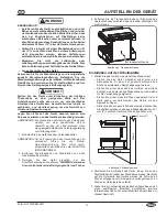
INSTALLATION
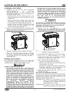
Wall Installation
1. Installthewallmountbracketprovidedwiththeunitontoa
solid, non-combustible surface using the appropriate
fasteners.Therearefivemountingholesonthewallmount
bracket.
• Make sure the fasteners are appropriate for the
installationsurfaceandtheweightoftheunit.
• locatetheunitdirectlyunderneathanexhausthoodif
possible. This will ensure total suction of steam
producedduringcooking.
• Makesuretheunitisattheproperheightinanarea
convenientforuse.
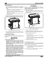
2. Alignthemountingslotsonthebackoftheunitwiththe
hooksonthewallmountbracket.Settheunitonthehooks.
Figure6.MountingSlotsonBackofUnit
3. Haveaqualifiedelectricianperformthenecessaryelectrical
connections(referto“ElectricalConnections”inthissection
foradditionalinformation).
Electrical Connections
The THERM-MAX Salamander must be hardwired to the
electrical supply or have the appropriate cord and/or plug
installed.
ELECTRIC ShOCk hAzARD:
• Units supplied without an electrical plug require field
installation of proper plug. Plug must be properly
grounded and of correct voltage, size, and
configuration for electrical specifications of unit.
Contact a qualified electrician to determine and install
proper electrical plug.
• Units supplied without an electrical cord and plug
require field installation of proper cord and plug or a
hardwired connection to on-site electrical system.
Connection must be properly grounded and of correct
voltage, size, and configuration for electrical
specifications of unit. Contact a qualified electrician to
determine and install proper electrical connection.
• When installing a hardwired unit, a 2-pole or 3-pole
switch (depending on unit) must be installed between
unit and main electrical supply. The switch must be
rated properly and have contacts with a minimum
opening distance of 3 mm (1/8″).
• Unit must be connected to an equipotential system that
complies with the latest electrical standards.
Mounting Slots
WARNING
Make sure electrical supply matches the voltage and
frequency rating on the specification label. Incorrect
electrical supply may damage the unit.
hardwired Connection
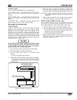
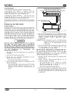
1. Removetheaccesspaneltoexposethepowerinletareaof
theunit.Itislocatedontherightrearsideoftheunitwhen
facingthecontrols.
Figure7.locationofPowerInlet
2. locatetheterminalblockinsidetheunit.
3. Bringpowerleadsfromaproperlysizedcircuitbreakeror
disconnectswitchthroughthepowerinletontheunit.
4. Maketheappropriateconnections.
• Usecopperwireonly.
• Tighten connections to a minimum of 4.25 newton
meters(40inchpounds).
• A grounding screw is provided near the electrical
terminals.Anequipmentgroundingconductormustbe
properlyconnectedtoit.
5. Replaceandsecuretheaccesspanel.
Cord and Plug Connection
Onunitssuppliedwithapowercord,connecttheproperplugto
thecord.Makesuretheplugisratedforthespecificloadand
theplugmatchesasuitablereceptacle.
NOTE: The specification label is located on the side of the unit
near the power inlet. See the label for verification of unit
electrical information.
NOTE: The plug and receptacle must be grounded in
accordance with current standards.
Power Inlet
Access Panel
NOTICE