background image


Operating instructions 

1.   It is assumed that the scanner and FlexColor software have 

been properly installed. 

2.   If not already done, lower the feed table 
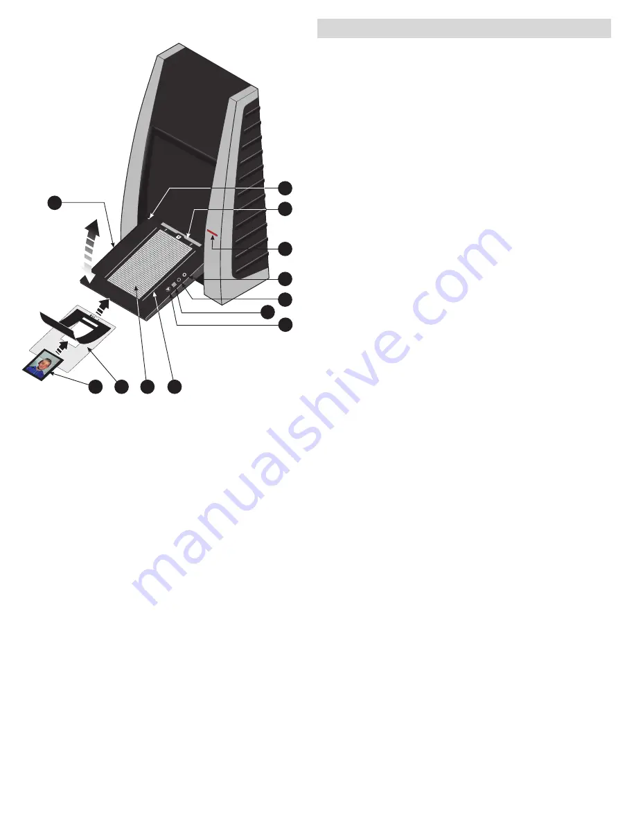
A

 to normal position. 

3.   Press the red power button 

F

 on the front of the scanner to 

switch it on. The green light 

G

 starts flashing. This means that 

no firmware has been downloaded yet. It will be downloaded 

automatically later when you first run the FlexColor program. 

4.   Turn on your computer and start the FlexColor program. The 

green light 

G

 will stop flashing indicating that firmware has 

been downloaded to the scanner. 

5.   Select the original holder 

K

 that matches your original: 

•   For transparencies, choose one of the holders that has a 

square hole in it. The original must completely fill the hole with 

no edges showing. Also, no edges of the original must extend 

past the outer edges of the holder. 

•   For reflectives, select the large A4/letter-size holder with the 

clear plastic layer. The feed table 

A

 must be in normal position. 

•   For 35 mm slide frames use the optional 35 mm slide mount 

holder. The feed table 

A

 must be adjusted to horizontal posi-

tion (see diagram). This is obtained by lifting the table slightly 

upwards while pushing it gently into the scanner.  


NOTE! Each original holder has it’s own unique identification 

code (a combination of small rectangular holes at the holder’s 

leading edge). These codes, combined with the scanner’s abili-

ty to detect the feed table position, ensure that the scanner will 

not operate unless the feed table position matches the selected 

original holder. 

6.   Place the original holder 

K

 with the slotted tab facing into the 

scanner. For transparencies, the flexible magnetic retaining 

flap must face upwards. For reflectives, the clear plastic sheet 

must face upwards. Make sure that the original holder fits 

between the appropriate guides 

C

 or 

D

 on both sides of the 

light table. 

7.   Slide the holder gently into the slot 

E

 at the top of the feed 

table. It will slip about ½ cm (¼ inch) into it. Do not press too 

hard. It slips in very easily and is held in place by a magnetic 

clasp. To remove the holder, simply pull it gently backwards. 

8.   Lift the retaining flap of the original holder and place your 

original 

L

 as follows: 

•   For transparencies, place your original with the emulsion side 

down. The original must completely fill the hole with no edges 

showing and with a minimum overlap of 2 mm along each 

edge. Also, no edges of the original must extend past the outer 

edges of the holder. Use the grid on the light table 

B

 to help 

line up the image. 


For transparency holders, the top retaing flap is magnetic, 

which will hold the original fast. 

•   For reflectives (Flextight X5 only), make sure that no part of the 

original extends past the edge of the holder. Use the dotted 

A

B

K

L

C

FLEXT

IGHT

 ORIG

INAL 

HO

LDER

PATE

NT PEN

DING

I

J

D

E

G

H

F

9

Summary of Contents for Flextight X5

Page 1: ...User Manual Flextight X5 X1 English v 1 5 ...

Page 2: ...ectrical Requirements Installation Procedure FireWire Interface Operating Instructions 9 Resolutions 10 True Resolutions Calibrating the Scanner 11 Focus Calibration 12 White Calibration for Reflectives 13 The Light Tubes 14 Cleaning the External Surface of the Scanner 16 Disposal 16 Technical Specifications 16 FCC Notice 17 CE Declaration of conformity 18 Flextight X1 18 Flextight X5 19 ...

Page 3: ...om profes sional photographers and production environments alike Developed around Hasselblad s patented virtual drum design and flexible magnetic holder and incorporating a 3x8000 optic CCD sensor and a Linos Rodenstock lens both scanners are fast easy to use and offer unparalleled image quality They also feature a new time saving facility an Auto Scan button which with one press automati cally de...

Page 4: ...d moving parts that can cause injury System requirements Below are the basic hardware requirements for the PC or Macintosh system to which the scanner is to be connected For information about the processor operating system RAM and harddisk requirements please refer to the Software Reference manual that comes with the FlexColor software Screen resolution of minimum 800 x 600 pixels with true colors...

Page 5: ...urn the unit on off F Power indicator Green Remains lit when ready to scan Flashes when first installed to indicate that firmware must be loaded it will be loaded automatically when you run FlexColor G Motor drive indicator Yellow Lights when the scanner is repositioning the optics to scan in a new format or when drum is repositioning H Scan indicator Red Lights when scanning Do not touch the scan...

Page 6: ... the optics that focuses the image of the original on the CCD sensor F Upper light source Illuminates reflective originals Flextigh X5 only G Prism module Focuses the light from various angles and thereby removes or heavily reduces dust and scratches in the scanned image Flextigh X5 only H Lower light source Illuminates transparent originals I Drum Rotates the original into the scanner and transpo...

Page 7: ...se Flextight with any power source outside the specified range The scanner and all devices attached to the scanner computer moni tor FireWire devices etc must be grounded i e use a three point electrical connec tion Note that the power supply may emit a low hissing sound when plugged in but not connected to the scanner This is normal and will not damage the power supply or scanner Installation pro...

Page 8: ...nner in the direction of the arrow B 2 While maintaining this pulling action raise the table until it is in the hori zontal position as in the illustration or a little higher Note that it requires a simultaneous pulling and raising action to reach this correct position 3 Finally push the table gently back towards the scanner in the direction of arrow C ensuring that both of the protruding lugs D s...

Page 9: ...ectangular holes at the holder s leading edge These codes combined with the scanner s abili ty to detect the feed table position ensure that the scanner will not operate unless the feed table position matches the selected original holder 6 Place the original holder K with the slotted tab facing into the scanner For transparencies the flexible magnetic retaining flap must face upwards For reflectiv...

Page 10: ...w the clear sheet must slip under each of these tabs as shown 10 Go to your computer and follow the directions given in the FlexColor software manual to take a preview make settings and take the final scan Alternatively you can press the scan button on the light table This will initiate a 3F scan according to your 3F settings Resolutions True Resolutions The table below shows the max resolutions i...

Page 11: ...m mechanism The focus calibration is stored in the scanners flash PROM so it is retained when you move the scanner to a new computer See Focus Calibration on page 12 for more information White calibration is only required for reflective scans it is done automatically for transparencies During calibration the scanner scans a white target to establish the white point along the full length of the sca...

Page 12: ... Focus Calibration 1 Locate the Focus sheet that came with your scanner It is a 8 x 9 cm 3 x 3 5 square of transparent black and white film 2 Mount the film into the 6 x 6 original holder with the text reading normally as shown Place the sheet as straight as possible Use the scanners light table grid and the corners marked on the sheet to help align it 3 Select Focus Calibration from the Maintenan...

Page 13: ...19 x 219 mm 8 6 x 8 6 If you have lost the white calibration sheet then you can use a flat non textured perfectly white piece of paper of the same dimensions 2 Your scanner came with several clear plastic layers for the reflective original holder If you have used the reflective holder before make sure that there are no finger prints or other marks on the plastic layer Replace the layer with a new ...

Page 14: ...re proceeding 3 Remove the two allen screws A one in each side using a 2 5 mm Allen key Do not remove any other screws 4 Press the back panel down app 5 mm and lift out using the handle B 5 Turn the feed table to upright position 6 Locate the tube to be replaced and dismount the plug C 7 Remove the defective tube Press the flaps backwards to release the tube E Pull the tube gently out of the holde...

Page 15: ...PRESS PULL OUT PULL OUT PRESS A B D C E G H F A 15 ...

Page 16: ...nction switch on off switch Status indicator LED s Drum Force 1 kg 2 2 lbs Operating Environment Operating Temperature 10 35 C 50 95 F Recommended Working Temperature 10 25 C 50 77 F Humidity 20 80 RH no condensation Storage Environment Temperature 0 50 C 32 122 F Relative humidity 20 80 RH no condensation Originals Transparencies from 35 mm to 4 x 5 inches 1 mm thick Reflectives up to 220 x 310 m...

Page 17: ...en the equipment is operated in a commercial environment This equipment generates uses and can radiate radio frequency energy and if not installed and used in accordance with the instruction manual may cause harmful interference to radio communications Operation of this equipment in a residential area is likely to cause harmful interfer ence in which case the user will be required to correct the i...

Page 18: ...CE Declaration of conformity 18 ...

Page 19: ...CE Declaration of conformity 19 ...

Page 20: ... commitment by Hasselblad AB Hasselblad AB assumes no responsibility or liability for any errors or inaccuracies that may appear in this manual Hasselblad AB assumes no responsibility or liability for loss or damage incurred during or as a result of using Hasselblad software or products Hasselblad Imacon FlexColor and Flextight are trademarks of Hasselblad AB Macintosh Mac OS and FireWire are regi...

Reviews: