17 |
P a g e
4.0 OPERATION
4.3 Refrigerant Sight Glass/
Moisture Indicator
A liquid-line sight glass/moisture indicator
has been installed to help you identify when
the system is low on refrigerant and to assist
the refrigeration mechanic when recharging
the system.
The sight glass/moisture
indicator is located at the
filter drier and is visible
when the service panel is
removed. When the
compressor is running,
bubbles flowing through
the sight glass indicate
that the Haskris system
is low on refrigerant.
Turbulence and bubbles inside the sight
glass are normal immediately after the
compressor turns on, and immediately after
it turns off. The sight glass should be clear
when the compressor is energized and
running.
4.4 Refrigerant Pressure Control
The refrigerant pressure control is a safety
device. The refrigerant pressure control de-
energizes the compressor motor when
refrigerant operating pressures are outside
the safe limits set by Haskris. The pressure
control can be found at the base of the
Haskris system.
NOTE:
Adjustments to the safe operating limits
of any refrigeration pressure control
should be made only after a qualified
refrigeration technician installs
refrigerant pressure gauges on the high
and low sides of the refrigeration system.
Low Pressure Control
All refrigerated platforms include a low
pressure control. This control, whether
single or part of a dual control, de-energizes
the refrigerant compressor when a
significant amount of refrigerant has leaked
out of the system, or when a restriction has
occurred in the refrigeration circuit. The low
pressure control also serves as an added
level of freeze-protection. The low pressure
control automatically resets when the
refrigerant pressure increases to a safe
level.
High Pressure Control
All refrigerated platforms include a high-
refrigerant pressure safety cutout with
manual
reset. The high pressure control de-
energizes the refrigerant compressor when
there is insufficient airflow through an air-
cooled condenser. The high pressure control
must be manually reset after the refrigerant
pressure decreases to a safe level.
Summary of Contents for OPC 12
Page 7: ...4 P a g e 2 0 INSTALLATION 2 2 System Location Continued ...
Page 8: ...5 P a g e 2 0 INSTALLATION ...
Page 15: ...12 P a g e 2 0 INSTALLATION ...
Page 26: ...23 P a g e 6 0 WARRANTY 5 0 MAINTENANCE ...
Page 27: ...24 P a g e 6 0 WARRANTY 5 0 MAINTENANCE ...
Page 28: ...25 P a g e 6 0 WARRANTY 5 0 MAINTENANCE ...
Page 29: ...26 P a g e 6 0 WARRANTY 5 0 MAINTENANCE ...
Page 30: ...27 P a g e 6 0 WARRANTY 5 0 MAINTENANCE ...
Page 32: ...29 P a g e 6 0 WARRANTY 5 0 MAINTENANCE ...
Page 33: ...30 P a g e 6 0 WARRANTY 5 0 MAINTENANCE 6 1 Standard Product Warranty 6 0 WARRANTY ...
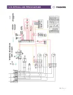
Page 35: ...32 P a g e 6 0 WARRANTY 7 0 ELECTRICAL AND PIPING DIAGRAMS ...
Page 36: ...33 P a g e 6 0 WARRANTY 7 0 ELECTRICAL AND PIPING DIAGRAMS ...


