


MACH
®
Gas Fired Boiler
27
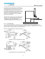
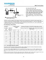
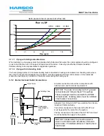
Delta pressure loss in pressure at a flow rate
3.7.1.1
Piping with Refrigeration Machines
When installed in a two-pipe system that provides both chilled and hot water, the control system should be configured
so as to limit the time rate of change of temperature at the boiler. Consult your authorized Harsco Industrial,
Patterson-Kelley boiler representative for application guidance.
3.7.1.2
Piping with Air Handling Units
The boiler piping system of a hot water heating boiler connected to heating coils located in air handling units, where
they may be exposed to refrigerated air circulation, must be equipped with flow control valves or other automatic
means to prevent gravity circulation of the boiler water during the cooling cycle.
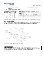
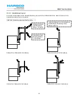
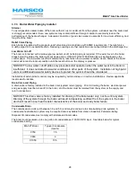
3.7.2 Boiler Inlet and Outlet Connections
All water connections should be in compliance with
national, state and local code requirements.
Adapters from Victaulic to NPT are available from Harsco
Industrial, Patterson-Kelley.
The bottom connection to the boiler is the INLET and
must be used for the return from the system.
The top connection to the boiler is the OUTLET and must
be connected as the supply to the system.
Flow vs. DP
0
2
4
6
8
10
12
14
0
20
40
60
80
100
120
Flow (gpm)
DP (ft)
Isolating
Valve
Strainer
Relief Valve
Isolating Valve
Outlet
(to system)
Inlet
(from system)
Boiler
Drain
Valve
Condensate
Trap (Piped to
drain)*
Building
Drain
NOTICE! The boiler is furnished with 2” grooved
connections and Victaulic Style 75 Couplings.
These couplings must be used with the EPDM
Victaulic seals. Isolating valves must be installed
in both water connections.
NOTICE! Condensate Trap must be piped to
drain in accordance with all national, state and
local codes. If installed outdoors, it must be field
heat traced.
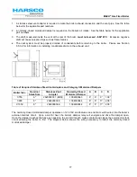
C750
C900
C1050