Harrington CF4 Owner'S Manual Download Page 8

.

I

I

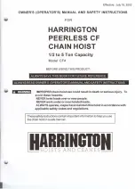
2. Main Specifications

~2 to I

~

ton

2 to 3 ton

5 ton

@

b-

c

d

~

I

I

d

Any lift of chain is available on request. Because Harrington chains are specially heat-treated, only authentic Harrington

chains should be used on your hoist. Never attempt to lengthen your chain by attaching additional chain links with anyother

means. Harrington can supply almost any length of chain desired. Simply specify the length of chain desired when ordering.

i

8

.1

Wt. for

Min.

Chain

Test

Shipping

Load

Add.

Cap.

Distance

Pull to

OVer-

Model Code

(U.S.

Std. Lift

Between Lift Full

haul

Load

Net Wt.

Wl

Chain

One

b

d

9

ton)

m (ft.)

Hooks: C

Load

Ratio

(U.S.

kg (Ib)

(approx.)

Fall

Foot of

mm (in)

m (ft)

mm(in)

mm (in)

kg (Ib)

ton)

kg (Ib)

(Lines)

Lift

kg (Ib)

CF4 CFO05

1/2

3.0(10) 325(12.8) 30(66)

19

.625

10(22)

11(24)

1

1.5(3.3)

150(5.9) 3.0(9.8)

27(1.06)

CF4 CF010

1

3.0(10) 370(14.6) 36(79)

31

1.25

12(26)

13(28)

1

1.8(4.0)

174(6.9)

3.0(9.8)

29(1.14)

CF4 CF015 1 1/2 3.0(10) 440(17.3) 42(92)

41

1.88

17(37)

18(39)

1

2.1(4.6)

203(8.0) 3.0(9.8)

34(1.34)

CF4 CF020

2

3.0(10) 510(20.1) 40(88)

63

2.50

21(46)

22(48)

2

2.7(6.0)

204(8.0) 3.0(9.8)

36(1.42)

CF4 CF030

3

3.0(10) 590(23.2) 46(101)

81

3.75

28(61)

30(66)

2

3.2(7.1)

240(9.4) 3.0(9.8) 42.5(1.67)

CF4 CF050

5

3.0(10) 620(24.4) 46(101)

134

6.25

37(81)

39(85)

3

4.3(9.5) 342(13.5) 3.0(9.8) 46.5(1.83)

Summary of Contents for CF4

Page 1: ...D OWNER S OPERATOR S MANUAL AND SAFETY INSTRUCTIONS IMPROPERchain hoist use could result in death or serious injury To avoid these hazards NEVERhoist loads over or near people NEVERwork under or near...

Page 2: ...I I I I I I 2 j...

Page 3: ...PECIFICATIONS 8 3 OPERATION 9 3 1 SafetyConsideration 9 3 2 Operation 9 3 3 Hoist Storage 9 4 INSPECTION 10 j 4 1 Outl ine 1 0 4 2 DailyInspection 10 4 3 Periodic Inspection 11 5 MAINTENANCE 16 5 1Lub...

Page 4: ...ortloadsoverornearpeople I J NEVER NEVER work near or under hoisted loads ALWAYS let people around you know when a lift is about to begin ALWAYS ALWAYS read Owner s Operator s manual and safety instru...

Page 5: ...ad and see the hoist s label for the hoist s rated capacity be sure that the load is properly seated in the saddle of the hook keep the load from hitting the chain use two hoists which have rated capa...

Page 6: ...e a hoist if the hook latch is missing or broken I lift a load unless it is directly underthe hook I I L splice a hoist chain use non authentic Harrington chains on the hoist usethe hoist chain as asl...

Page 7: ...throwahoist use a hoist without a nameplate ofwarning label or with illegible nameplateofwarning label remove orobscure thewarning tag use modified or deformed hooks use a motor to operate a manual ho...

Page 8: ...Std Lift Between Lift Full haul Load Net Wt Wl Chain One b d 9 ton m ft Hooks C Load Ratio U S kg Ib approx Fall Foot of mm in m ft mm in mm in kg Ib ton kg Ib Lines Lift kg Ib CF4 CFO05 1 2 3 0 10 32...

Page 9: ...d chain clockwise 3 To lower the load pullhand chain counterclockwise NOTE 3 3 Hoist Storage The clicking sound of the pawl when a load is being raised indicates normal operation IMPROPER chain hoist...

Page 10: ...hes are in place and in proper condition 5 Make sure the openings of the upper and lower hooks are not too wide that the swivel rotates freely and that the hook latch is inposition and works normally...

Page 11: ...e inthe following opening of embossed marks at table J hook timeof purchasewith a slide calipers Check visually I Twist is large enoughto be IReplacethe hook detected visually 2 Wear Measure c and d I...

Page 12: ...amage nutsorbolts Fittingsof 1 4 44 56 66 75 6 Idlesheave Holdthe loadchain Rotation is W IRepair T rotation 55 61 with both hands and not smooth 70 turn the idle sheave by moving the chain up and dow...

Page 13: ...t Split pin 36 Disassemble and service Disassemble and service Wheel stopper 34 Snap ring 28 Wheel stopper pin 35 U nut 25 Pawl spring 26 Pawl pin 24 Socket bolt 22 13 I Item I Inspection Method I Di...

Page 14: ...by foreign matter 29 3 Wear on Measurewith slide Thickness not uniform and I Replace the part friction plate calipers friction plate worn more 32 than 0 5mm 020 in For all types Normal thickness 3 0m...

Page 15: ...chain ICheckvisually guide 20 Excessive wear or press mark 2 Flaw on guide roller 20 A Check visually Does not turn freely 3 Deformation of stripper 21 Checkvisually Stripper is crushed or the tip is...

Page 16: ...d grease and replace with new grease standard grease at annual inspection Temperature range of standard grease is 20 C 4 F to 60 C 140 F If the hoist is used at temperatures below 20 C 4OF or above 60...

Page 17: ...frequently than normal in a corrosive environment use machine oil equivalent to ISO VG45 or 58 clean chain with an acid free solvent only to remove rust or abrasive dust build up After cleaning lubri...

Page 18: ...e wheel stopper pin and wheel stopper 34 from the pinion 14 6 Remove the hand wheel 33 from the pinion 14 by turning the hand wheel counterclockwise 7 Remove two friction plates 32 ratchet disc 30 and...

Page 19: ...d top pin 3 from the body B 11 15 Remove pinion 14 chain guide 20 or guide rollers 20 A stripper 21 tailpin 40 and load chain 42 16 Remove the frame 13 17 Take load sheave 18 out ofthe load gear 19 18...

Page 20: ...them together on the ball bearing C 17 Body B 11 Load gear 19 Ball bearing B 16 Load sheave 1 8 4 Apply new grease to the load gear 19 5 Put frame 13 on the body B 11 according to pattern 6 Insert th...

Page 21: ...in guide 20 or guide rollers for 1 2 ton 20 A on the frame 13 t 9 Put stripper 21 on the frame 13 10 Insert pinion 14 shaft from its gear side through the frame 13 and into ball bearing 8 16 11 Insert...

Page 22: ...ith fingers Socket bolt 22 A Body B 11 U nut 23 15 Insert pawl pin 24 into the body A 10 and fix it with the U nut 25 16 Apply machine oil to the pawl pin 24 and join pawl spring 26 and the pawl 27 re...

Page 23: ...ocket bolt 22 19 Remove the dirt from the hand wheel 33 and apply machine oil to the threaded part Assemble onto the pinion shaft 14 by turning it clockwise as far as possible 20 Place wheel stopper 3...

Page 24: ...n the body A 10 and fix them with the spring washers 39 and screws 38 23 Put a hoist with Body B 11 side up Place the slack end of the load chain between body A 10 and body B 11 Then insert tail pin 4...

Page 25: ...published repair centerpriortoshippingproductforwarrantyevaluation Anexplanationofthe complaintmustac companythe product Product must be returned freightprepaid Upon repair the product willbe covered...

Page 26: ...I II ADDITIONAL PARTS FOR 2 3 AND 5 TON CAPACITY I ji I II II IJ II c till 8 5T 26...

Page 27: ...15B CF800030B CF800050B 12 Blank with rivets 1 CF4800005 CF4800010 CF4800020 CF4800015 CF4800030 CF4800050 13 Frame 1 CF105005 CF105010 CF105015 CF111005 CF111010 CF111015 CF111050 14 Pinion 1 CF41110...

Page 28: ...I...

Page 29: ...ompleteSet I 1 59 TopYokeA I 1 60 TopYokeB I 1 61 IdleSheave 1 62 Shaft 1 I I63 Spring Pin 1 64 Socket Bolt 3 9091296 65 U Nut 3 9098508 66 Top Hook Assy 1 67 Latch Assembly I 1 68 Bottom Hook Complet...

Page 30: ...n Hoists Inc 401 West End Avenue Manheim PA 17545 1703 Phone 717 665 2000 Toll Free 800 233 3010 Fax 717 665 2861 Harrington Hoists Western Division 2341 Pomona Rincon Rd 103 Corona CA 92880 6973 Phon...

Reviews: