44
1019658 11/2014
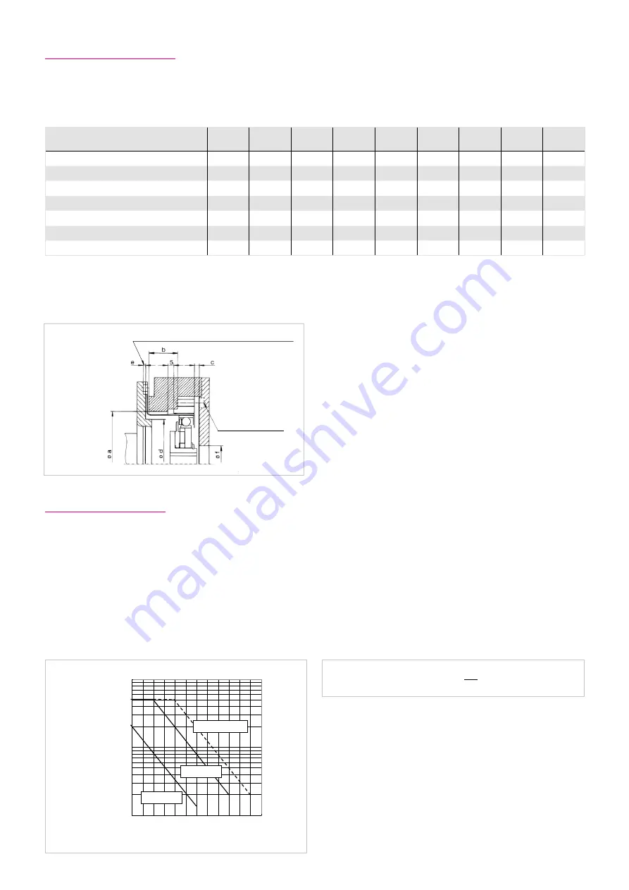
5.7.2 Grease Reservoir
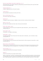
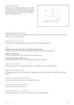
For assembly please ensure that the grease reservoir is filled up with grease (dimension c and ø d in table 44.1 and
illustration 44.2).
Table 44.1
Illustration 44.2
Size
14
17
20
25
32
40
45
50
58
ø a
38
45
53
66
86
106
119
133
154
b
14.6
16.4
17.8
19.8
23.2
28.6
31.9
34.2
40.1
c*
1
1
1.5
1.5
1.5
2
2
2
2.5
c**
3
3
4.5
4.5
4.5
6
6
6
7.5
ø d
31
38
45
56
73
90
101
113
131
e
1.7
2.1
2
2
2
2
2.3
2.5
2.9
ø f
16
26
30
37
37
45
45
45
56
Maximum centering length
Countersink for
mounting bolt heads
* Horizontal and Vertical - Wave Generator below
** Vertical - Wave Generator above
5.7.3 Grease Change
To change the grease the component set should be completely disassembled and cleaned before regreasing. Fresh grease
should be applied generously to the inside of the Flexspline, the Wave Generator bearing, the Oldham coupling and the teeth
of the Circular Spline and Flexspline.
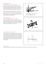
In illustration 44.3, the grease change interval depending on the grease temperature is given. The number of allowable revolu-
tions of the input shaft which represents the grease change interval can be estimated as shown in the example. This means,
that for a temperature of SK-1A or SK-2 grease of 40° C a change should take place after approx. 8.5 x 10
8
revolutions of the
input shaft. All grease change data refers to rated speed and rated torque.
Illustration 44.3
L
GT
= Number of Wave Generator revolutions until grease change
L
GTn
= see diagram
T
r
= Rated torque
T
av
= Average torque
L
GT
= L
GTn
.
(
)
3
T
r
T
av
Equation 44.4
1E+08
1E+09
1E+10
20
40
60
80
100
120
140
Grease Temperature [°C]
1E+10
1E+09
1E+08
Number of W
G r
evolutions
20 40 60 80 100 120 140
Flexolub A1
4B No. 2
SK1A, SK2


