background image

12

3-90-70738R9_08/13

wATEr COIl OPTION

Example 2:

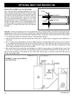
 Circulating pump method. Used when the distance is more than ten feet or when the stove is on a higher level 

than the existing water heater. In addition to a circulator, you may want to add a aquastat to control the pump according to 

water temperature. This is not necessary if the circulator is left run continuously. Another option is a gate valve placed near 

the circulator to control the rate of flow.
1.  Turn off the water heater and the water supply to it. Drain the tank completely.
2.  Remove the Temp/Pressure relief valve and discard. Install a short ¾” nipple and tee (1) along with a new Temp/Pressure 

relief valve.

3.  Remove the drain valve, at the bottom of the storage tank. Install a ¾” nipple and tee, and reinstall the drain valve to the 

tee (4).

4.  Install a circulating pump (6) as shown. Run ¾” copper tubing from the circulator to the lower leg of the coil. This is where 

the optional gate valve (5) can be installed.

5.  Install a ¾” tee and a 150 lb. pressure relief valve (7) in the top leg within 2 feet of the top outlet of the water coil.
6.  Complete the copper line by running it back to the tee at the top of the water tank, making sure to install a vent elbow 

and automatic air vent (2) at the high point of the line. The optional aquastat can be installed in this line a maximum of 

six feet from the stove. The aquastat must be a “close on temperature rise” type and must be wired and set to turn on the 

circulator when the water temperature reaches 120˚ Farenheit. 

The system is now ready to be refilled and power restored to the water heater ONLY after the tank is filled.

EXAmPlE 2: Circulator method. 

(more than 10 feet.)

Summary of Contents for SF 250

Page 1: ...nicipal building department fire department fire prevention bureau etc to determine the need for a permit Cette guide d utilisation est disponible en francais Chez votre concessionnaire de Harman save...

Page 2: ...ed information Safety Considerations 3 Specifications 4 Assembly 5 Installation 6 Chimney Venting 7 8 Operating Instructions 9 Maintenance 10 Optional Bent Hot Water Coil 11 12 Testing Label 13 Warran...

Page 3: ...to operate It has been verified that creosote will ignite at 650 degrees fahrenheit It is the owner s responsibility to follow these recommendations This stove consumes air when it is burning if your...

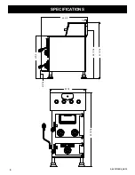
Page 4: ...4 3 90 70738R9_08 13 7 8 35 3 4 5 13 16 32 5 8 36 11 16 42 15 16 20 1 2 42 15 16 Specifications...

Page 5: ...ker Handle The shaker handle installs onto the shaker handle mount using the two hex bolts and washers provided Firebricks The SF250 uses 14 standard firebricks as shown below These standard firebrick...

Page 6: ...oor protection should extend 8 to the rear and either side and 16 in front of the stove The floor protection should also extend 2 to either side of the chimney connector to the wall where the connecto...

Page 7: ...ything within ten feet It also must extend three feet above the point where it intersects or exits the roof line In order to have a properly operating solid fuel heating system the chimney must be cap...

Page 8: ...square inches Increased by 25 would be 63 square inches or approximately a 9 round flue In general for round liners it is recommended that they not be increased by more than one inch from that of the...

Page 9: ...low time in between Loading Coal should only be added when there is a reasonably hot fire The coal bed should be bright and vigorous If the fire is burning hot and there is a deep bed of coals full lo...

Page 10: ...is cleaned After cleaning the chimney any debris will be at the bottom by the clean out door Open the clean out and vacuum the loose debris Clean the smoke pipe from the chimney to the stove using a m...

Page 11: ...the event of over heating 4 Remove the drain valve at the bottom of the storage tank Install a nipple and tee and reinstall the drain valve to the tee 4 Run copper tubing with the necessary fittings...

Page 12: ...tall a nipple and tee and reinstall the drain valve to the tee 4 4 Install a circulating pump 6 as shown Run copper tubing from the circulator to the lower leg of the coil This is where the optional g...

Page 13: ...3 90 70738R9_08 13 testing label This appliance is also approved for installation into a shop S A M P L E...

Page 14: ...me construction warranty coverage begins on the date of first occupancy of the dwelling or six months after the sale of the product by an independent authorized HHT dealer distributor whichever occurs...

Page 15: ...his warranty does not cover the following Changes in surface finishes as a result of normal use As a heating appliance some changes in color of interior and exterior surface finishes may occur This is...

Page 16: ...16 3 90 70738R9_08 13 Date Of Service Performed By Description Of Service Service Maintenance Log...

Page 17: ...17 3 90 70738R9_08 13 notes...

Page 18: ...00 Recycled Paper At Harman we build each product to a standard not a price Signature of Boxer Your premium quality hearth product designed and assembled by the experienced and skilled members at Harm...

Reviews: