background image

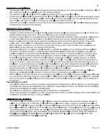
A qualified service person recommended by your Harman 

dealer should conduct an annual inspection and maintenance 

of your clarity, its venting, and the installation to keep it 

running safely and efficiently. The following procedures 

should be performed only by a qualified service person. The 

gas supply should be turned off whenever a maintenance 

procedure is performed.

if the glass front, side doors, or front access door are 

removed for servicing, they must be replaced prior to op-

erating the clarity.

Removing the Glass for Replacement

to remove the glass panel in the door, remove upper and 

lower glass clips and lift the glass out. Use only authorized 

harman replacement glass components available from your 

harman dealer.

Replacing the Gasket

The Clarity has 5/8" diameter fiberglass gasket in the front 

door. should it ever need replacement, use only the proper 

replacement  gasket  that  is  available  from  your  harman 

dealer. to replace the gasket, follow this procedure.

1. open the door

2. remove the existing gasket and clean its channel with 

a scraper or wire brush.

3. Lay a thin bead of high temperature silicone the entire 

length of the channel.

4. Lay the gasket in the channel with sufficient pressure 

that is stays in place.

5. trim the excess from the end of the gasket so that it 

butts snugly against the other end without leaving a gap. 

seal the end joint with high temperature silicone.

6. Close the door and apply firm pressure to seat the gasket 

evenly throughout.

Cleaning the Glass

the glass may be cleaned with ordinary household glass 

cleaner and a soft cloth or paper towel.

WARNING: Never clean the glass when it is hot. Do 

not use abrasive cleaners on the glass.

Inspecting the Venting 

an inspection of both the inner and outer pipes of the 

venting system should be made during the annual service 

appointment. they must have no blockage and be in good 

repair. the vent manufacturer's instructions may provide 

specific suggestions or details on vent inspection. Any sec

-

tions that are taken apart for the inspection must be reas-

sembled and sealed as required.

Cleaning the Log Set and Firebox

During the annual inspection and maintenance appoint-

ment, the service person should clean dust, lint, and any light 

accumulation from the logs and the firebox area. An extra-

soft brush should be used on the logs as they are extremely 

fragile; a vacuum cleaner may be used on the firebox. If at 

any time the logs cannot be removed or installed without 

forcing, the cause must be found. the logs must never be 

forced.

Removing the Front 

see directions on page 15.

Removal & Re-installation of the Log Set for Clean-

ing

caution: the ceramic logs are durable when handled 

and installed properly. however, they are delicate and may 

be damaged easily if not handled with care. handling dam-

age to the ceramic logs is not covered by warranty.

Do not hanDLe LoGs WhiLe theY are hot. 

aLLoW PLentY oF tiMe For the stove to cooL 

coMPLeteLY BeFore hanLDinG.

Remove the Branch

Detach the branch from the two locator pins and remove 

it. Brush it gently and carefully place it to one side.

Remove the Center Log

Lift the center log and remove it. Brush it gently and 

carefully place it to one side with the branch.

Remove the Ember Strips

carefully remove the ember strips, clean them, and place 

them with the other logs.

Remove the Side Brick Panels

Carefully remove first one side panel, and then the other. 

clean and place to side.

Remove the Back Log and Back Brick Panel

Finally, carefully remove these two components as a single 

piece. Brush them gently and place them to the side.

Finish  the  procedure  by  vacuuming  the  interior  of  the 

firebox, then re-install the logs and secure the glass front 

following the procedures on page 15&16.

The appliance area must be kept clear and free from 

combustible materials, gasoline and other flammable 

vapors and liquids.

MAINTENANCE

Summary of Contents for Clarity 929 DV

Page 1: ...type of gas indicated on the rating plate This appliance is not convertible for use with other gases unless a certified kit is used Cet appareil peut tre install dans une maison pr fabriqu e mobile d...

Page 2: ...ing the Gas Flame 19 OPERATION 20 How to Light the Fire 20 How to Turn Off the Fire 20 Lighting Instructions 21 Maintenance 22 Removing the Glass 22 Replacing the Gasket 22 Cleaning the Glass 22 Inspe...

Page 3: ...ion and the accessibility of the gas and electrical supply must all be considered In addition selecting a location that takes advantage of the building s natural air flow is also desirable to maximize...

Page 4: ...idth and depth of the appliance Clearance to back wall 3 75 mm IMPORTANT NOTICE Due to high temperatures the Clarity Direct Vent Gas Heatershould be located out of traffic and away from furniture and...

Page 5: ...nsult your local building codes before beginning the installation and follow the manufacturer s instructions exactly The following Simpson Duravent GS 4 X 6 5 8 venting components are approved for use...

Page 6: ...om the center line of the terminal E Clearance to unventillated soffit F Clearance to outside corner G Clearance to inside corner H Clearance to each side of center line extended above meter regulator...

Page 7: ...VENTING Vent cap regulations These Diagrams along with the table detail the restrictions on the vent terminal location...

Page 8: ...ermination 14 984 1284 Horizontal Square Termination 980 1280 Vertical Termination 991 1291 Vertical Termination High Wind 950 1250 Vinyl Siding Standoff 1222D Only available from Harman 8 x 5 to 6 5...

Page 9: ...ipe Length Galvanized 4DT 9B 9 Pipe Length Black 4DT 12 12 Pipe Length Galvanized 4DT 12B 12 Pipe Length Black 4DT 18 18 Pipe Length Galvanized 4DT 18B 18 Pipe Length Black 4DT 24 24 Pipe Length Galva...

Page 10: ...V4EBR90 990B SV5EBR90 1290B Adjustable Decorative Square Cathedral Support SV4CSB 941 SV5CSB 1241 Collar for the Decorative Square Cathedral Support SV4AC n a SV5AC n a Decorative Black Plate square S...

Page 11: ...section female female MFL18 24 flex section female female MFL2 36 flex section female female MFL3 48 flex section female female MFL4 Elbows 45 solid elbow section female male connectors EEL45 90 elbo...

Page 12: ...7 12 to 12 12 pitch roof MRF 12 Flashing and storm collar for 7 12 to 12 12 pitch roof Bulk pack of 6 MRF1206 Horizontal Vent Restrictors For 8 14 horizontal vent run MHVR8 For 15 24 horizontal vent...

Page 13: ...ion female mal PEXT4 72 rigid section female male PEXT6 Flex Sections 12 flex section female female connectors PFL1 18 flex section female female PFL18 24 flex section female female PFL2 36 flex secti...

Page 14: ...upport plate support ring PSPXT 8 8 Support plate support ring Bulk pack of 6 PSP806 Flashing and storm collar for 1 12 to 7 12 pitch roof PRF7 Flashing and storm collar for 1 12 to 7 12 pitch roof Bu...

Page 15: ...1 88b 2003 CSA2 33b 2003 test methods and the resulting ITS WHI product certfication The code Authority Having Jurisdiction must be consulted prior to proceeding assembly Remove and Unwrap the Log Set...

Page 16: ...p of the back log and the other on the top of the center log Secure the Glass Front NOTE The glass front is heavy Lift it carefully to pre vent damage Center the glass on the opening and suspend it in...

Page 17: ...N TEST ALL JOINTS FOR LEAKS BE FORE OPERATING Gas Pressure Requirements Correct gas pressure and the use of a properly sized gas supply line are essential for the safe and efficient per formance of th...

Page 18: ...h of the wire RECOMMENDED WIRE GAUGES Maximum Wire Length Gauge 100 14 60 16 40 18 25 20 15 22 Connecting the Cordset The Clarity Direct Vent Gas Heater must be installed in accordance with local code...

Page 19: ...factory setting Turn the other two screws as needed to increase or decrease the brightness and length of the flame turning counterclockwise will decrease the flame turning clockwise will increase the...

Page 20: ...control knob counterclockwise to ON 12 Place the ON OFF THERMOSTAT switch in the ON position or in the THERMOSTAT position if the optional thermostat is used 13 Turn on the electric power to the heate...

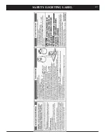
Page 21: ...21 Safety lighting Label...

Page 22: ...They must have no blockage and be in good repair The vent manufacturer s instructions may provide specific suggestions or details on vent inspection Any sec tions that are taken apart for the inspecti...

Page 23: ...de c blage peuvent entra ner un fonctionnement inad quat et dan gereux S assurer que l appareil fonctionne ad quatement une fois l entretien termin DO NOT USE THIS HEATER IF ANY PART HAS BEEN UNDER W...

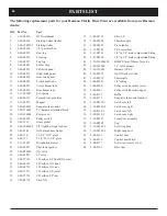
Page 24: ...35 3 40 08236 3 40 08237 3 40 08401 3 40 08232 3 40 08233 3 40 08234 3 40 08693 3 40 08225 3 40 08226 3 31 965487 3 40 00141 3 31 08225 3 20 408412 3 20 326007 3 20 326004 3 20 00907 3 42 2312 3 44 10...

Page 25: ...25 3 58 21 18 52 63 27 60 64 61 62 17 51 59 17 16 16 57 24 17 1 53 54 55 56 49 50 parts...

Page 26: ...26 Clarity Burner Module Exploded View 38 36 47 12 13 14 39 48 42 46 40 41 31 32 33 52 53...

Page 27: ...kPa 5 0 1 25 11 0 2 74 Maximum Output Btu hr 0 4500 ft 0 1375 m 31 200 32 100 AFUE seasonal efficiency minimum venting 71 6 73 8 Steady State Efficiency max input blower on High 80 2 83 3 MINIMUM CLEA...

Page 28: ...installing the fuel conversion remove the Glass door and the log set to gain access to the burner module Remove the burner tubes by sliding to the left while lift ing upward Remove the burner cover pl...

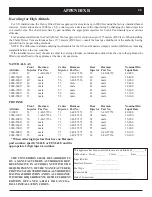
Page 29: ...900 4000 5000 49 male 57 male 42 male 35 400 5000 6000 50 male 57 male 42 male 34 000 6000 7000 50 male 57 male 43 male 32 600 7000 8000 51 male 58 male 43 male 31 300 8000 9000 51 male 58 male 44 mal...

Page 30: ...30...

Page 31: ...31...

Page 32: ......

Reviews: