


SYSTEM CONFIGURATION
SYSTEM CONFIGURATION
SYSTEM CONFIGURATION 27
SYSTEM CONFIGURATION 27
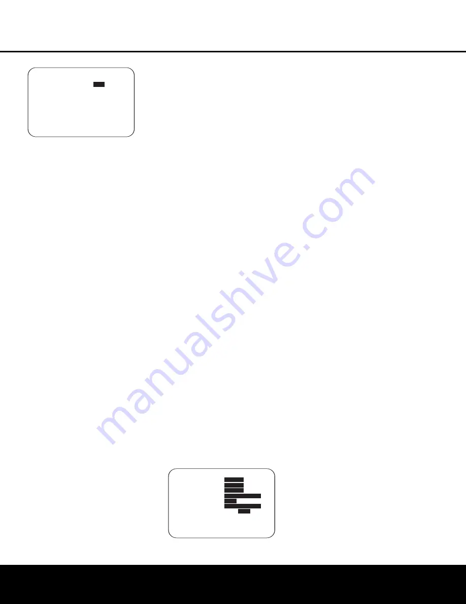
Figure 16
If you have already run the EzSet/EQ calibration sys-
tem, the first line of the menu enables you to hear
the difference between the settings established by
EzSet/EQ. The default setting is
ON
, which plays the
incoming source with the EzSet/EQ settings. To hear
the system in a Bypass mode, with none of the equal-
ization filters in the circuit path, press the
‹
/
›
Navigation Button
o
so that
OFF
is highlighted.
Note that once changed, this setting will remain until
you change it again in this menu. While you may want
to use this menu option to hear the difference that
EzSet/EQ makes, we recommend that you leave the
setting on to take advantage of the benefits of
EzSet/EQ’s advanced room correction technology.
The
EZSET ADJUST
line on the menu
enables you to set the system’s Tilt, or high-frequency
boost. To make this adjustment, first make sure that
EZSET EQ
line is set to
ON
, as this item is not
available when EzSet EQ is not in the signal path.
When the cursor is on the
EZSET ADJUST
line, press the
Set Button
q
, and then press the
‹
/
›
Navigation Button
o
to enter the desired
setting. When you have completed your adjustment,
press the
›
Navigation Button
o
to move the
cursor down to the
BACK TO MANUAL
SETUP
line and press the
Set Button
q
.
Note on Manual Setup Menus:
Each of the four
major manual setup menus (Speaker Size, Speaker
Crossover, Delay Adjust and Channel Adjust) includes
a line that reads
EZSET SETTINGS
. When
the default setting of
OFF
is shown you are able to
make any required adjustments that are available on
that menu. However, you may change the setting to
ON
at any time to recall the settings established when
EzSet/EQ was last run. It is also important to note that
when the EzSet/EQ settings are in use, the AVR will
not allow any changes to be made. To trim the settings
press the
‹
/
›
Navigation Button
o
until the cur-
sor is on the
EZSET SETTINGS
line on
the menu in use and press the
‹
/
›
Navigation
Button
o
to change the setting to
OFF
. This will
allow you to make changes to the settings on that
menu.
Speaker Setup
Although using EzSet/EQ to enter the settings for
speaker “size” and crossover point, you may wish to
make changes to those settings, or to manually enter
a complete speaker profile for your system. In addi-
tion, for systems where you with to have separate
speaker configuration settings for each input, rather
than use the same settings for all inputs, you may also
configure that option in these menus. Two separate
menus are used to enter this information, and you
may change the data on either or both, as needed.
The
SPEAKER SIZE
menu tells the AVR
about the bass reproduction capabilities of your
speakers. This, in turn, determines which speakers
receive bass information that is derived from audio
tracks or specifically intended for reproduction by
low-frequency-capable speakers by the use of a low-
frequency effects (“LFE”) channel in digital program
sources. In addition, by telling the AVR whether speakers
are available for the Surround Back channels, the
information on this menu is used to determine which
surround modes may be used (e.g., modes such as
Dolby Digital EX, Dolby Pro Logic IIx, or DTS-ES,
requiring SBL/SBR speakers, are only available when
a speaker is present in those channels).
The
SPEAKER X-OVER
menu is used to fur-
ther tailor the bass management system by determin-
ing the frequencies at which bass information is sent
to a specific speaker position. This menu also contains
settings to route LFE information and to set the sub-
woofer high-pass filter order.
To configure the speakers in your system for use with
the AVR 635, or to check the settings entered by
EzSet/EQ, check the settings on the various sub-menu
groups on the
MANUAL SETUP
menu, starting
with the
SPEAKER SIZE
menu (Figure 17)
and then check the other menus’ settings. To do this,
go to the Manual Setup Menu (Figure 16) by first
pressing the
OSD Button
U
to recall the Master
Menu (Figure 1). Next, press the
‹
/
›
Navigation
Button
o
until the cursor is on the
MANUAL
SETUP
line on the menu in use and press the
Set
Button
q
. When the
MANUAL SETUP
Menu is shown, press the
‹
/
›
Navigation Button
o
again until the cursor is on the
SPEAKER
SIZE
line and press the
Set Button
q
.
Figure 17
On the
SPEAKER SIZE
menu (Figure 17),
you will see either the factory default settings or, if
EzSet/EQ has been run, the settings recorded by the
test results. In the case for the main speaker channels,
each speaker position (front left/right, center, surround
left/right and surround back left/right) you have the
option of telling the system if the speakers used are
“small” or “large”. These descriptions do not describe
the actual physical size of the speakers, but rather
refer to the type of speaker. For each of these set-
tings, select
LARGE
when the speakers in a partic-
ular position are traditional full-range loudspeakers.
Use the
SMALL
setting for smaller, frequency-limited
“satellite” speakers that do not reproduce sounds
below 60Hz. In all cases except the front left/right
speakers you may also select
NONE
. This tells the
system that no speakers are present at the particular
position, allowing the AVR to select the correct sur-
round modes that are compatible with the number
of speakers installed. For example, in order to use
the Dolby Digital EX, Dolby Pro Logic IIx, DTS-ES
Logic 7/7-channel and 7 Stereo modes, you must
have either Large or Small speakers entered as the
setting for the Surround Back channels.
If you are in doubt as to which setting best describes
your speakers consult the specifications in the speakers’
owner’s manual, visit the speaker manufacturer’s web
site or ask the dealer or installer from whom you pur-
chased the speakers.
Begin your changes to the speaker setup process
by making certain that the cursor is pointing at the
LEFT
/
RIGHT
line, which sets the configuration
for the front left and right speakers. If you wish to make
a change to the front speakers’ configuration, press the
‹
/
›
Navigation Button
o
so that either
LARGE
or
SMALL
appears, matching the appropriate
description from the definitions shown above.
IMPORTANT NOTE:
If a change is made to this, or
any speaker position, when you press the
‹
/
›
Navigation Button
o
, an on-screen warning mes-
sage will appear reminding you that EzSet/EQ must be
run. This is necessary to integrate the changed param-
eter with the EzSet/EQ test results. Make all desired
setting changes on the
SPEAKER SETUP
and
SPEAKER X-OVER
menus once, and then
run EzSet/EQ after all manual adjustments are com-
pleted.
When
SMALL
is selected, low-frequency sounds will
be sent only to the subwoofer output. If you choose this
option and there is no subwoofer connected, you will
not hear any low-frequency sounds from the front
channels.
When
LARGE
is selected, a full-range signal will be
sent to the front left and front right outputs. Depending
on the choice made in the
SUBWOOFER
line in
* SPEAKER SIZE *
→
→
LEFT/RIGHT:
SMALL
CENTER :
SMALL
SURROUND :
SMALL
SURR BACK :
NONE MAIN
SUB MODE :
SUB
SUB SIZE :
10in/250mm
EZSET SETTINGS:
OFF
ON
BACK TO MANUAL SETUP
* MANUAL SETUP *
→
→
EZSET EQ :
OFF
ON
EZSET ADJUST
SPEAKER SIZE
SPEAKER XOVER
DELAY ADJUST
CHANNEL ADJUST
BACK TO MASTER MENU
AVR 635 OM 12/2/04 3:28 PM Page 27


