Harman Kardon AVR 140 Owner'S Manual Download Page 20

20

SYSTEM CONFIGURATION

System Configuration

going to the front left/right speakers, or you may
configure it so that the subwoofer feed is
activated.
The factory default setting is to have the sub-
woofer turned off for this mode, but you may
change that setting by following these steps:

1. Press the 

Speaker Button

6

'

.

2. Press the 

Set Button

F

@

to activate the

configuration menu.

3. Press the 

/

¤

Buttons

D

on the remote or

the 

/

Buttons

7

on the front panel to select

the desired option.

SUB NONE

turns off the

feed to the subwoofer, while 

SUB <L+R>

turns it on.

4. When the desired setting has been entered,
press the 

Set Button

F

@

to return to nor-

mal operation.

Stereo-Digital Mode

When the Stereo-Direct (Bypass) mode is in use a
full range signal is always sent to the front
left/right speakers. By its nature, that option does
not pass the signal through the AVR’s digital sig-
nal processing, creating the requirement for full-
range speakers. If your front speakers are band-
width limited, “satellite”speakers, we recommend
that you do NOT use the Bypass mode, but rather
use the 

DSP SURROUND OFF

mode for

stereo listening.

To listen to programs in the two-channel stereo
mode while taking advantage of the bass man-
agement system, press the 

Stereo Mode

Selector

until 

SURROUND OFF

appears in the 

Main Information Display

Ò

and the DSP and 

SURR. OFF

Surround

Mode Indicators

(

both light up. When only

the 

SURR. OFF

Surround Mode

Indicators

(

is lit you are in the Stereo-Direct

(Bypass) mode.

When this mode is in use, the front left/right
speakers and subwoofer may be configured to
meet the requirements of your specific speakers
using the steps shown in the Speaker Setup sec-
tion below.

Speaker Setup

This menu tells the AVR which type of speakers
are in use. This is important as it adjusts the set-
tings that decide whether your system will use
the "5-channel" or "6-channel/7-channel"
modes, as well as determine which speakers
receive low-frequency (bass) information. For
each of these settings use the 

LARGE

setting if

the speakers for a particular position are tradi-
tional full-range loudspeakers that are capable of
reproducing sounds below 200Hz.
Use the 

SMALL

setting for smaller, frequency-

limited satellite speakers that do not reproduce
sounds below 200Hz. Note that when “small”
speakers are used, a subwoofer is required to
reproduce low-frequency sounds. Remember that

the “large” and “small” descriptions do not refer
to the actual physical size of the speakers, but to
their ability to reproduce low-frequency sounds. If
you are in doubt as to which category describes
your speakers, consult the specifications in the
speakers’ owner’s manual, or ask your dealer.

At last, this menu also makes you chose if the
speaker setting will be the same for each input
source (

GLOBAL

), or will be set differently for

each input (

INDEPENDENT

).

Notes:

• When "Independent" is selected for the speak-

er settings (see below), they need to be made
for each input individually and you can deter-
mine which speaker should be used depending
on the input source selected. So it´s possible
e.g. to turn off the Center and/or the Sub with
any music source selected and to use them
with any movie input source.

• With the currently selected input all speaker

settings will be copied to all other surround
modes (as far as speakers are used with them)
and need not be repeated when another sur-
round mode is selected with that input.

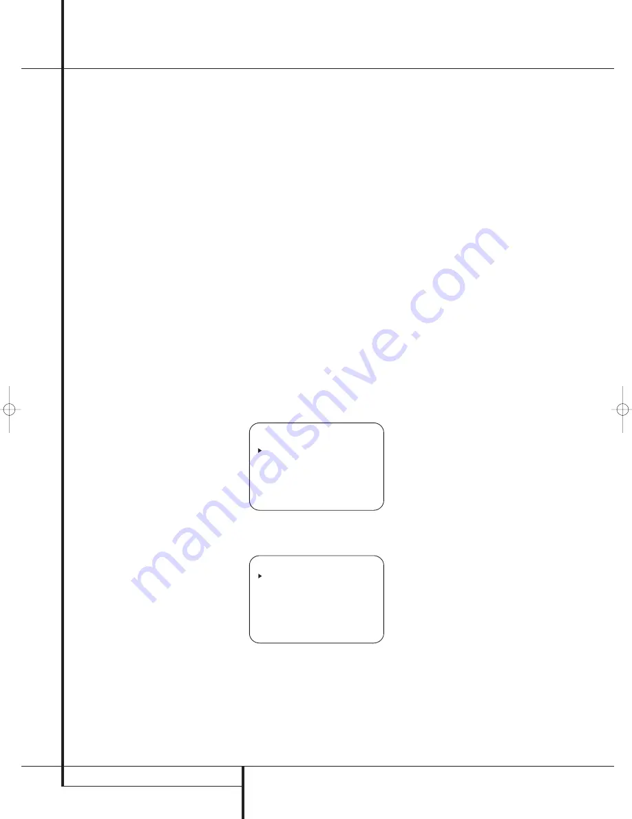
It is easiest to enter the proper settings for the
speaker setup through the 

SPEAKER SIZE

menu (Figure 7). So press the 

OSD Button

L

to bring up the 

MASTER MENU

(Figure 1),

and then press the 

¤

Button

D

three times

so that the cursor is on the 

MANUAL SETUP

line.

Figure 6

At this point, press the 

Set Button

F

and

select the 

SPEAKER SIZE

menu (Figure 7).

Figure 7

1. Before you start the speaker setting, you
should determine if you want all inputs being
configured with the same speaker size setting
(

GLOBAL

) or if all inputs should be configured

individually (

INDEPENDENT

).

To configure all inputs for "Global" or "Inde-
pendent" press the 

Button

D

twice so that

the cursor is next to the 

BASS MGR

line.

This setting allows you to use the same speaker
configuration for all inputs, or to have different
settings for each input. In most cases the factory
default setting of 

GLOBAL

will be appropriate,

as most listeners do not need to have individual-
ized speaker settings. However, some listeners,
particularly those with full-range front speakers
that are used for both movies and music may
prefer that different speaker settings be used
when listening to music through a CD player as
opposed to a movie from a DVD player, VCR or
cable/satellite set top.

If you wish to customize the speaker size individ-
ually to each input, make certain that the cursor
is on the 

BASS MGR

line and press the 

/

Buttons

E

so that 

INDEPENDENT

appears in highlighted video. When this setting is
entered all speaker size settings will be shown
with their factory default size in the menu and all
other inputs will turn to 

INDEPENDENT

too.

Now you should enter the speaker size settings
prefered for the input selected, as described
below. Remember that in this case the size set-
tings just entered will apply to the current input
ONLY, and you will need to go back to the

INPUT

menu to select another input, and then

return to this menu page again to change the
settings for the next input. Repeat the procedure
for any input where you wish to have a set of
speaker configuration different from the default
settings.

NOTE:

When the 

INDEPENDENT

setting is

activated, you may assign different speaker size
settings to each input to accommodate different
bass management settings that match your pref-
erences with the type of program material nor-
mally used with a particular source (for example,
when movies are played from DVD and music
from a CD player). However, the actual speaker
crossover settings are set only once and do not
change with the input selection. The reason is
that, while bass management preferences may
vary, the actual speakers remain the same,
regardless of the bass-management and redirec-
tion settings.

2. Begin the speaker size setup process by making 
certain that the cursor is pointing toward the

LEFT/RIGHT

line, which sets the configura-

tion for the front left and right speakers. If you
wish to make a change to the front speakers’ 
configuration, press the 

/

Buttons

E

so

that either 

LARGE

or 

SMALL

appears, match-

ing the appropriate description from the definitions
shown above.

When 

SMALL

is selected, low-frequency front

channel sounds will be sent only to the subwoofer
output. If you choose this option and there is no
subwoofer connected, you will not hear any low-
frequency sounds with front channel signals.

When 

LARGE

is selected, a full-range output

will be sent to the front left and front right 
outputs. Depending on the choice made in 

  *   S P E A K E R   S I Z E   *

L E F T / R I G H T : S M A L L

C E N T E R         : S M A L L

S U R R O U N D     : S M A L L

S U R R   B A C K   : S M A L L

S U B W O O F E R   : S U B

B A S S   M G R     : G L O B A L

B A C K   T O   M A N U A L   S E T U P

  *   M A N U A L   S E T U P   *

S P E A K E R   S I Z E

S P E A K E R   X - O V E R

D E L A Y   A D J U S T

C H A N N E L   A D J U S T  

B A C K   T O   M A S T E R   M E N U

25339_AVR140_Eng_2  30/08/05  9:56  Side 20

Summary of Contents for AVR 140

Page 1: ...AVR 140 Audio VideoReceiver OWNER S MANUAL Power for the Digital Revolution...

Page 2: ...ng the Remote 37 Programming the Remote with Codes 37 Direct Code Entry 37 Auto Search Method 37 Code Readout Table of Contents Typographical Conventions In order to help you use this manual with the...

Page 3: ...ility the AVR features connections for four video devices all with both composite and S Video inputs Two additional audio inputs are available and a total of six digital inputs and two outputs make th...

Page 4: ...ventilation slots on the top of the unit or place objects directly over them Due to the weight of the AVR 140 and the heat generated by the amplifiers there is the remote possibility that the rubber p...

Page 5: ...connected 5 Surround Mode Group Selector Press this button to select the top level group of surround modes Each press of the button will select a major mode grouping in the following order Dolby Mode...

Page 6: ...page 20 for more information on configuring speakers The letters inside each of the center boxes display active input channels For standard analog inputs only the L and R will light indicating a ster...

Page 7: ...al FM antenna to this terminal Tape Inputs Connect these jacks to the PLAY OUT jacks of an audio recorder Tape Outputs Connect these jacks to the RECORD INPUT jacks of an audio recorder Subwoofer Outp...

Page 8: ...total power consumption of all devices connected to the accessory outlets should not exceed 100 watts from the Unswitched Outlet and 50 W from the Switched Outlet AC Power Cord Connect the AC plug to...

Page 9: ...s Tuner Mode Direct Button Tuning Up Down OSD Button Dolby Mode Select Button DTS Digital Mode Selector Logic 7 Mode Select Button Transport Controls Spare Button Skip Up Down Buttons Stereo Mode Sele...

Page 10: ...re information about surround modes Note that this button is also used to tune channels on your TV VCR and Sat receiver when the appropriate source is selected using the device Input Selector 4 B Nigh...

Page 11: ...DVD or 10 CD CDR Clear Button Press this button to clear incorrect entries when using the remote to directly enter a radio station s frequency Memory Button Press this button to enter a radio station...

Page 12: ...occur Cables that are run inside walls should have the appropriate markings to indicate listing with any appropriate testing agency standards Questions about running cables inside walls should be ref...

Page 13: ...udible visible when the VCR is playing connect the Out plugs to the In jacks on the AVR and turned around If the adapter plugs are not labeled in that way pay attention to the signal flow direc tions...

Page 14: ...iding RGB signals on a SCART output as e g most DVD players do and you want to use that RGB signal this SCART output must be connected directly to your TV Although the AVR can switch three way video s...

Page 15: ...seated in the listening position Using these guidelines you ll find that it takes some experimentation to find the correct location for the front speakers in your particular installation Don t be afr...

Page 16: ...are not shown in the Infor mation Display When the full OSD menu system is used OSD ON will appear in the Main Information Display to remind you that a video display must be used When the semi OSD sy...

Page 17: ...rst make certain that the cursor is pointing to the COMPONENT IN line on the menu screen and then press the Navigation Button E until you see the desired input in the highlighted video The clicking no...

Page 18: ...ial flag signal in the digital audio data stream the EX mode will be selected automatically It may also be selected using this menu or through the front panel or remote con trols as shown on page 29 A...

Page 19: ...her resolution materials that are present due to the higher sampling rate automatically See page 26 and 27 for a complete explanation of the DTS modes On the LOGIC 7 menu the selection choices made wi...

Page 20: ...e 7 So press the OSD Button L to bring up the MASTER MENU Figure 1 and then press the Button D three times so that the cursor is on the MANUAL SETUP line Figure 6 At this point press the Set Button F...

Page 21: ...ween the front left and front right outputs For optimal performance when no surround speakers are in use the Dolby 3 Stereo mode should be used When you are using surround back speakers with your syst...

Page 22: ...er in frequency than your subwoofer is capable of reproducing To prevent unwanted sounds from being sent to subwoofers that can not handle them and which do not have a built in low pass filter the LFE...

Page 23: ...tive speaker positions by pressing the Button D again and use the Buttons E to change the setting Remember that this last adjustment will only be needed when you have surround back speakers installed...

Page 24: ...put balance for the mixing cir cuit that creates a 6 1 output when 7 1 modes such as Logic 7 7 1 are used 6 After checking for speaker placement let the test noise circulate again and listen to see wh...

Page 25: ...input and repeat the level adjustment described above This will also allow you to com pensate level differences between speakers that may be different with each surround mode or to increase or decreas...

Page 26: ...that are recorded with matrix surround or even with normal stereo mode creating separate rear left and rear right signals in any case The Pro Logic II mode creates compelling five channel surround so...

Page 27: ...zed HALL 2 concert hall with stereo and even pure mono sources VMAx Near When only the two front channel loudspeakers are used Harman s patented VMAx mode VMAx Far delivers a three dimensional sound s...

Page 28: ...to your home entertainment system on a temporary basis As the input source is changed the new input name will appear momentarily as an on screen display in the lower third of the video display The inp...

Page 29: ...Harman s patented VMAx mode delivering a virtually three dimensional sound space with two speakers only Surround modes are selected using either the front panel controls or the remote To select a new...

Page 30: ...Display or on screen display When the digital source is playing the AVR will automatically detect whether it is a multichannel Dolby Digital or DTS source or a conventional PCM signal which is the st...

Page 31: ...ormation shown on the back of a DVD package In some cases you will see indi cation for 2 0 0 even when the disc contains a full 5 1 or 3 2 1 signal When this happens check the audio output settings fo...

Page 32: ...ny digital input of the AVR only as long as Surround Off mode is selected possible with a PCM source only But the analog two channel signal even of a Dolby Digital not DTS source the Downmix to Stereo...

Page 33: ...d then press the Set Button F if you wish to go back to the main menu to make other adjustments If you have no other adjustments to make press the OSD Button L to exit the menu system NOTE The output...

Page 34: ...To turn off the semi OSD system you will need to make an adjustment in the ADVANCED SELECT menu Figure 11 To start the adjustment press the OSD button L to bring the MASTER MENU to the screen Press t...

Page 35: ...on 1 Press the AM FM Tuner Select button 6 on the remote to select the tuner as an input The tuner may be selected from the front panel by either pressing the Input Source Selector until the tuner is...

Page 36: ...O TYPE NO TEXT or NO TIME message after the individual time out In any FM mode the RDS function requires a strong enough signal for proper operation Program Search PTY An important feature of RDS is i...

Page 37: ...e with the Auto Search Method Note on Using the AVR remote with a Harman Kardon CD Recorder As shipped from the factory the remote is programmed for controlling Harman Kardon CD players It can also co...

Page 38: ...vices press the appropriate Input Selector 4 to change the remote from control over the AVR to the additional product When you press any of these buttons it will briefly flash in red to indicate that...

Page 39: ...port Control Functions P Play Stop Fast Forward Rewind Pause and Record for a VCR DVD or CD will operate in con junction with one of the other devices controlled by the remote For example while using...

Page 40: ...7 Set Set Enter 28 Move Adjust Right Right 29 Digital Exit Digital Input Select Open Close 30 Move Adjust Down Down 31 Delay Prev Ch Delay Adjust Return Open Close 32 1 1 1 1 33 2 2 2 2 34 3 3 3 3 35...

Page 41: ...enu Menu Menu Menu Menu 26 Left Left Left Left Scroll 27 Set Enter Enter Enter Enter Select 28 Right Right Right Right Scroll 29 Digital Exit Exit Exit Exit Exit Repeat 30 Down Down Down Down 31 Delay...

Page 42: ...rvice depot SYMPTOM CAUSE SOLUTION Unit does not function when Main No AC Power Make certain AC power cord is plugged Power Switch 1 is pushed into a live outlet Check to see if outlet is switch contr...

Page 43: ...NTSC Input Level Impedance 1Vp p 75 ohms Output Level Impedance 1Vp p 75 ohms Video Frequency Response Composite and S Video 10Hz 8MHz 3dB Video Frequency Response Component 10Hz 50MHz 3dB General Pow...

Page 44: ...Surround L R Crossover Surround Back Crossover LFE Setting Table 1 Input Settings Table 2 Audio Setup Tone Control Settings Table 3 Delay Settings CONTROL SETTING Tone In Out Bass Treble If the GLOBAL...

Page 45: ...INTRODUCTION 45...

Page 46: ...rossways Park Drive Woodbury New York 11797 www harmankardon com Harman Consumer Group International 2 route de Tours 72500 Ch teau du Loir France 2005 Harman Kardon Incorporated Part No OM P N CQX1A1...

Reviews: