Harman Kardon AVR 140 Owner'S Manual Download Page 16

16

SYSTEM CONFIGURATION

System Configuration

Once the speakers have been placed in the room
and connected, the remaining steps are to pro-
gram the system configuration memories. With
the AVR two kind of memories are used, those
associated individually with the input selected,
e.g. surround modes, and others working global-
ly for all inputs selected like speaker output lev-
els, crossover frequencies or delay times used by
the surround sound processor.

First Turn On

You are now ready to power up the AVR to begin
these final adjustments.

1. Plug the 

Power Cable

into an unswitched

AC outlet.

2. Press the 

Main Power Switch

1

in until it

latches and the word “OFF” on the top of the
switch disappears inside the front panel. Note
that the 

Power Indicator

3

will turn

orange, indicating that the unit is in the
Standby mode.

3. Remove the protective plastic film from the

main front-panel lens. If left in place, the film
may affect the performance of your remote
control.

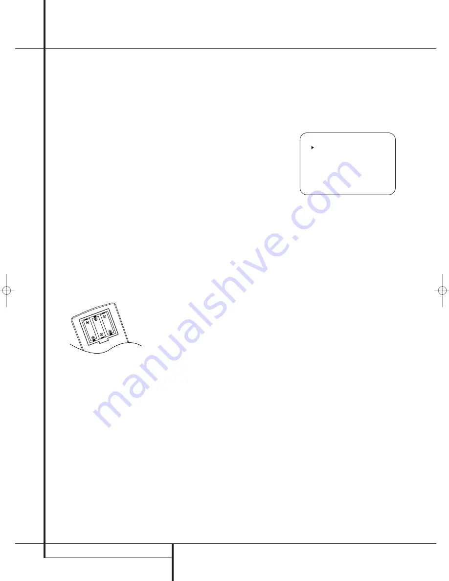
4. Install the three supplied AAA batteries in the

remote as shown. Be certain to follow the (+)
and (–) polarity indicators that are on the top
of the battery compartment.

5. Turn the AVR on either by pressing the 

System

Power Control

2

or the 

Input Source

Selector

%

on the front panel, or via the

remote by pressing the 

Power On Button

3

,

AVR Selector

5

or any of the 

Input

Selectors

46

on the remote. The 

Power

Indicator 

3

will turn blue to confirm that the

unit is on, and the 

Main Information

Display

Ò

will also light up.

NOTE:

After pressing one of the 

Input Selector

buttons

4

to turn the unit on, press the 

AVR

Selector

5

to have the remote control the AVR

functions.

Using the On-Screen Display

When making the following adjustments, you
may find them easier to make via the unit’s on-
screen display system. These easy-to-read
displays give you a clear picture of the current
status of the unit and facilitate speaker, delay,
input or digital selection you are making.

To view the on-screen displays, make certain you
have made a connection from the 

Video Monitor

Out

jack 

on the rear panel to the composite

or S-Video input of your TV or projector. In order
to view the AVR’s displays, the correct video input
must be selected on your video display. Note that
the on-screen menus are not available when a
component video display is in use.

IMPORTANT NOTE:

When viewing the on-screen

menus using a CRT-based projector, plasma display
or any direct-view CRT monitor or television, it is
important that they not be left on the screen for an
extended period of time. As with any video display,
but particularly with projectors, constant display of
a static image such as these menus or video game
images may cause the image to be permanently
“burned into” the CRT. This type of damage is not
covered by the AVR warranty and may not be cov-
ered by the projector TV set’s warranty.

The AVR has two on-screen display modes,
“Semi-OSD” and “Full-OSD.” When making con-
figuration adjustments, it is recommended that
the Full-OSD mode be used. This will place a
complete status report or option listing on the
screen, making it easier to view the available
options and make the settings on the screen. The
Semi-OSD mode uses one-line displays only.

Note that when the full OSD system is in use, the
menu selections are not shown in the 

Infor-

mation Display

Ò

. When the full OSD menu

system is used,

OSD O N

will appear in the

Main Information Display

Ò

to remind you

that a video display must be used.

When the semi-OSD system is used in conjunc-
tion with the discrete configuration buttons, the
on screen display will show a single line of text
with the current menu selection. That selection
will also be shown in the 

Main Information

Display

Ò

.

The full OSD system can always be turned on or
off by pressing the 

OSD

button 

L

. When this

button is pressed the 

MASTER MENU

(Figure 1) will appear, and adjustments are made
from the individual menus. Note that the menus
will remain on the screen for 20 seconds after the
latest action was made on the screen menu, then
they will “time-out” and disappear from the
screen. The time-out may be increased to as
much as 50 seconds by going to the

ADVANCED SELECT

menu, and changing

the item titled 

FULL OSD TIME OUT

.

The semi-OSD system is also available as a sys-
tem default, although it may be turned off by

using the 

ADVANCED SELECT

menu. (See

page 34). With the semi-OSD system, you may
make adjustments directly, by pressing the but-
tons on the front panel or remote control for the
specific parameter to be adjusted. For example, to
change the digital input for any of the sources,
press the 

Digital Select Button

Û

G

and

then any of the 

Selector buttons

/

7

or

/

¤

D

on the front panel or remote.

Figure 1

System Setup

The AVR 140 features an advanced memory sys-
tem that enables you to establish different con-
figurations for the speaker configuration, digital
input, surround mode, delay times, crossover fre-
quencies and speaker setting for each input
source. To ease the speaker setting, the same
speaker setting can also be made for all inputs.
This flexibility enables you to custom tailor the
way in which you listen to each source and have
the AVR memorize them. This means, for example,
that you may associate different surround modes
and analog or digital inputs with different
sources, or set different speaker configurations
with the resultant changes to the bass manage-
ment system or the use of the center speaker
and/or the Subwoofer. Once these settings are
made, they will automatically be recalled
whenever you select that input.

The factory default settings for the AVR 140 have
all inputs configured for an analog audio input
except for the DVD input, where the 

Coaxial

Digital Input

is the default and the Video 2

input, where the 

Optical Digital Audio Input

is the default. Once the DSP processing sys-

tem is used for the first time for any input, the
speaker settings will automatically default to
“Small” at all positions with the subwoofer set to
“LFE.” The default setting for the surround modes
is Logic 7 Music, although Dolby Digital or DTS
will automatically be selected as appropriate
when a source with digital encoding is in use.

Before using the unit, you will probably want to
change the settings for most inputs so that they
are properly configured to reflect the use of digi-
tal or analog inputs and the surround mode asso-
ciated with the input. Remember that since the
AVR memorizes the settings for each input indi-
vidually, you will need to make these adjustments
for each input used. However, once they are
made, further adjustment is only required when
system components are changed.

* *   M A S T E R   M E N U   * *

    I N P U T   S E T U P

    A U D I O   S E T U P

    S U R R O U N D   S E L E C T

    M A N U A L   S E T U P

    A D V A N C E D

25339_AVR140_Eng_2  30/08/05  9:55  Side 16

Summary of Contents for AVR 140

Page 1: ...AVR 140 Audio VideoReceiver OWNER S MANUAL Power for the Digital Revolution...

Page 2: ...ng the Remote 37 Programming the Remote with Codes 37 Direct Code Entry 37 Auto Search Method 37 Code Readout Table of Contents Typographical Conventions In order to help you use this manual with the...

Page 3: ...ility the AVR features connections for four video devices all with both composite and S Video inputs Two additional audio inputs are available and a total of six digital inputs and two outputs make th...

Page 4: ...ventilation slots on the top of the unit or place objects directly over them Due to the weight of the AVR 140 and the heat generated by the amplifiers there is the remote possibility that the rubber p...

Page 5: ...connected 5 Surround Mode Group Selector Press this button to select the top level group of surround modes Each press of the button will select a major mode grouping in the following order Dolby Mode...

Page 6: ...page 20 for more information on configuring speakers The letters inside each of the center boxes display active input channels For standard analog inputs only the L and R will light indicating a ster...

Page 7: ...al FM antenna to this terminal Tape Inputs Connect these jacks to the PLAY OUT jacks of an audio recorder Tape Outputs Connect these jacks to the RECORD INPUT jacks of an audio recorder Subwoofer Outp...

Page 8: ...total power consumption of all devices connected to the accessory outlets should not exceed 100 watts from the Unswitched Outlet and 50 W from the Switched Outlet AC Power Cord Connect the AC plug to...

Page 9: ...s Tuner Mode Direct Button Tuning Up Down OSD Button Dolby Mode Select Button DTS Digital Mode Selector Logic 7 Mode Select Button Transport Controls Spare Button Skip Up Down Buttons Stereo Mode Sele...

Page 10: ...re information about surround modes Note that this button is also used to tune channels on your TV VCR and Sat receiver when the appropriate source is selected using the device Input Selector 4 B Nigh...

Page 11: ...DVD or 10 CD CDR Clear Button Press this button to clear incorrect entries when using the remote to directly enter a radio station s frequency Memory Button Press this button to enter a radio station...

Page 12: ...occur Cables that are run inside walls should have the appropriate markings to indicate listing with any appropriate testing agency standards Questions about running cables inside walls should be ref...

Page 13: ...udible visible when the VCR is playing connect the Out plugs to the In jacks on the AVR and turned around If the adapter plugs are not labeled in that way pay attention to the signal flow direc tions...

Page 14: ...iding RGB signals on a SCART output as e g most DVD players do and you want to use that RGB signal this SCART output must be connected directly to your TV Although the AVR can switch three way video s...

Page 15: ...seated in the listening position Using these guidelines you ll find that it takes some experimentation to find the correct location for the front speakers in your particular installation Don t be afr...

Page 16: ...are not shown in the Infor mation Display When the full OSD menu system is used OSD ON will appear in the Main Information Display to remind you that a video display must be used When the semi OSD sy...

Page 17: ...rst make certain that the cursor is pointing to the COMPONENT IN line on the menu screen and then press the Navigation Button E until you see the desired input in the highlighted video The clicking no...

Page 18: ...ial flag signal in the digital audio data stream the EX mode will be selected automatically It may also be selected using this menu or through the front panel or remote con trols as shown on page 29 A...

Page 19: ...her resolution materials that are present due to the higher sampling rate automatically See page 26 and 27 for a complete explanation of the DTS modes On the LOGIC 7 menu the selection choices made wi...

Page 20: ...e 7 So press the OSD Button L to bring up the MASTER MENU Figure 1 and then press the Button D three times so that the cursor is on the MANUAL SETUP line Figure 6 At this point press the Set Button F...

Page 21: ...ween the front left and front right outputs For optimal performance when no surround speakers are in use the Dolby 3 Stereo mode should be used When you are using surround back speakers with your syst...

Page 22: ...er in frequency than your subwoofer is capable of reproducing To prevent unwanted sounds from being sent to subwoofers that can not handle them and which do not have a built in low pass filter the LFE...

Page 23: ...tive speaker positions by pressing the Button D again and use the Buttons E to change the setting Remember that this last adjustment will only be needed when you have surround back speakers installed...

Page 24: ...put balance for the mixing cir cuit that creates a 6 1 output when 7 1 modes such as Logic 7 7 1 are used 6 After checking for speaker placement let the test noise circulate again and listen to see wh...

Page 25: ...input and repeat the level adjustment described above This will also allow you to com pensate level differences between speakers that may be different with each surround mode or to increase or decreas...

Page 26: ...that are recorded with matrix surround or even with normal stereo mode creating separate rear left and rear right signals in any case The Pro Logic II mode creates compelling five channel surround so...

Page 27: ...zed HALL 2 concert hall with stereo and even pure mono sources VMAx Near When only the two front channel loudspeakers are used Harman s patented VMAx mode VMAx Far delivers a three dimensional sound s...

Page 28: ...to your home entertainment system on a temporary basis As the input source is changed the new input name will appear momentarily as an on screen display in the lower third of the video display The inp...

Page 29: ...Harman s patented VMAx mode delivering a virtually three dimensional sound space with two speakers only Surround modes are selected using either the front panel controls or the remote To select a new...

Page 30: ...Display or on screen display When the digital source is playing the AVR will automatically detect whether it is a multichannel Dolby Digital or DTS source or a conventional PCM signal which is the st...

Page 31: ...ormation shown on the back of a DVD package In some cases you will see indi cation for 2 0 0 even when the disc contains a full 5 1 or 3 2 1 signal When this happens check the audio output settings fo...

Page 32: ...ny digital input of the AVR only as long as Surround Off mode is selected possible with a PCM source only But the analog two channel signal even of a Dolby Digital not DTS source the Downmix to Stereo...

Page 33: ...d then press the Set Button F if you wish to go back to the main menu to make other adjustments If you have no other adjustments to make press the OSD Button L to exit the menu system NOTE The output...

Page 34: ...To turn off the semi OSD system you will need to make an adjustment in the ADVANCED SELECT menu Figure 11 To start the adjustment press the OSD button L to bring the MASTER MENU to the screen Press t...

Page 35: ...on 1 Press the AM FM Tuner Select button 6 on the remote to select the tuner as an input The tuner may be selected from the front panel by either pressing the Input Source Selector until the tuner is...

Page 36: ...O TYPE NO TEXT or NO TIME message after the individual time out In any FM mode the RDS function requires a strong enough signal for proper operation Program Search PTY An important feature of RDS is i...

Page 37: ...e with the Auto Search Method Note on Using the AVR remote with a Harman Kardon CD Recorder As shipped from the factory the remote is programmed for controlling Harman Kardon CD players It can also co...

Page 38: ...vices press the appropriate Input Selector 4 to change the remote from control over the AVR to the additional product When you press any of these buttons it will briefly flash in red to indicate that...

Page 39: ...port Control Functions P Play Stop Fast Forward Rewind Pause and Record for a VCR DVD or CD will operate in con junction with one of the other devices controlled by the remote For example while using...

Page 40: ...7 Set Set Enter 28 Move Adjust Right Right 29 Digital Exit Digital Input Select Open Close 30 Move Adjust Down Down 31 Delay Prev Ch Delay Adjust Return Open Close 32 1 1 1 1 33 2 2 2 2 34 3 3 3 3 35...

Page 41: ...enu Menu Menu Menu Menu 26 Left Left Left Left Scroll 27 Set Enter Enter Enter Enter Select 28 Right Right Right Right Scroll 29 Digital Exit Exit Exit Exit Exit Repeat 30 Down Down Down Down 31 Delay...

Page 42: ...rvice depot SYMPTOM CAUSE SOLUTION Unit does not function when Main No AC Power Make certain AC power cord is plugged Power Switch 1 is pushed into a live outlet Check to see if outlet is switch contr...

Page 43: ...NTSC Input Level Impedance 1Vp p 75 ohms Output Level Impedance 1Vp p 75 ohms Video Frequency Response Composite and S Video 10Hz 8MHz 3dB Video Frequency Response Component 10Hz 50MHz 3dB General Pow...

Page 44: ...Surround L R Crossover Surround Back Crossover LFE Setting Table 1 Input Settings Table 2 Audio Setup Tone Control Settings Table 3 Delay Settings CONTROL SETTING Tone In Out Bass Treble If the GLOBAL...

Page 45: ...INTRODUCTION 45...

Page 46: ...rossways Park Drive Woodbury New York 11797 www harmankardon com Harman Consumer Group International 2 route de Tours 72500 Ch teau du Loir France 2005 Harman Kardon Incorporated Part No OM P N CQX1A1...

Reviews: