background image

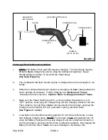
MAGNETIC

BIT HOLDER

CHUCK

LOCKING SWITCH (#12)

CHARGER PLUG

CHARGER

BIT

POWER SWITCH

(#11)

HANDLE

(#6, #7, #8, #9)

FIGURE C

To Charge The Cordless Screwdriver:

1.

NOTE:

 The Battery Pack (part #3) requires charging.  The first charge requires

10 to 12 hours

 charge time prior to using the Cordless Screwdriver.  Never

charge battery more than 12 hours for the initial charge.

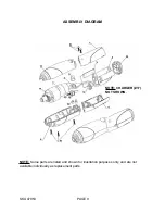
(See Assy. Diagram.)

2.

The Cordless Screwdriver should only be re-charged when the tool begins to run
slowly.

3.

When the Cordless Screwdriver requires re-charging, a 

5 hour

 charge allows the

tool to operate at full power.  Further charging to a 

maximum of


7 hours

 increases the tool’s use time.  

Caution: Never re-charge more than 7 hours.

4.

Make sure the Power Switch (part #11) on the Cordless Screwdriver is in its
“OFF” position.  Next, plug the Charger Plug into the Charging Socket of the tool.
Then, attach a 3-prong Plug Adapter (not provided) to the Charger, and plug the
Charger into the nearest 120 volt, grounded, 3-prong, electrical outlet.

(See Figures C, and A.)

5.

A red light on the Handle Assembly (parts #6, #7, #8, #9) will illuminate to show
that charging is taking place.  

NOTE:

 The Charger will not automatically turn off

when the Battery Pack (part #3) is fully charged, and the red light will remain on
until the Charger is disconnected from the Cordless Screwdriver. Re-charging the
Battery Pack more than 

7 hours

 can cause damage to the battery cells.

SKU 47953

PAGE 6

(#17)

Summary of Contents for Chicago Electric 47953

Page 1: ...isit our Web site at http www harborfreight com Copyright 2002 by Harbor Freight Tools All rights reserved No portion of this manual or any artwork contained herein may be reproduced in any shape or form without the express written consent of Harbor Freight Tools For technical questions please call 1 800 444 3353 ...

Page 2: ... WORK AREA CLEAN AND DRY Cluttered damp or wet work areas invite injuries 2 KEEP CHILDREN AWAY FROM WORK AREA Do not allow children to handle this product 3 STORE IDLE EQUIPMENT When not in use tools and equipment should be stored in a dry location to inhibit rust Always lock up tools and equipment and keep out of reach of children 4 DO NOT USE THIS PRODUCT IF UNDER THE INFLUENCE OF ALCOHOL OR DRU...

Page 3: ...e or repair damaged or worn parts immediately 11 REPLACEMENT PARTS AND ACCESSORIES When servicing use only identical replacement parts Only use accessories intended for use with this product Approved accessories are available from Harbor Freight Tools 12 MAINTAIN THIS PRODUCT WITH CARE Keep this product clean dry and keep all cutting bits sharp for better and safer performance 13 MAINTENANCE For y...

Page 4: ...roduct should only be connected to a 3 prong Adapter Plug not provided and a 120 Volt 3 hole electrical outlet that is protected by a Ground Fault Circuit Interrupter GFCI See Figure A CHARGER 3 PRONG ADAPTER PLUG 120 VOLT OUTLET FIGURE A 3 IF AN EXTENSION CORD not provided IS USED MAKE SURE TO USE ONLY UL APPROVED CORDS HAVING THE CORRECT GAUGE AND LENGTH See Figure B next page 4 PROTECT THE CHAR...

Page 5: ...erence or failure of the pacemaker UNPACKING When unpacking check to make sure all the parts shown on the Parts List on page 8 are included If any parts are missing or broken please call Harbor Freight Tools at the number shown on the cover of this manual as soon as possible OPERATING INSTRUCTIONS NOTE For additional references to the parts listed below refer to the Assembly Diagram on page 9 To A...

Page 6: ...7 hours increases the tool s use time Caution Never re charge more than 7 hours 4 Make sure the Power Switch part 11 on the Cordless Screwdriver is in its OFF position Next plug the Charger Plug into the Charging Socket of the tool Then attach a 3 prong Plug Adapter not provided to the Charger and plug the Charger into the nearest 120 volt grounded 3 prong electrical outlet See Figures C and A 5 A...

Page 7: ...be changed for driving and removing screws and sockets See Figure C 2 For the forward direction push the top of the Power Switch part 11 For the reverse direction push the bottom of the Power Switch See Figure C INSPECTION MAINTENANCE AND CLEANING 1 CAUTION Always turn the Power Switch part 11 to its OFF position and unplug the electrical Charger from its electrical outlet before performing any in...

Page 8: ... SHE IS QUALIFIED TO REPLACE ANY PARTS OF THE PRODUCT IN FACT THE MANUFACTUER AND OR DISTRIBUTOR EXPRESSLY STATES THAT ALL REPAIRS AND PARTS REPLACEMENTS SHOULD BE UNDERTAKEN BY CERTIFIED AND LICENSED TECHNICIANS AND NOT BY THE BUYER THE BUYER ASSUMES ALL RISK AND LIABILITY ARISING OUT OF HIS OR HER REPAIRS TO THE ORIGINAL PRODUCT OR REPLACEMENT PARTS THERETO OR ARISING OUT OF HIS OR HER INSTALLAT...

Page 9: ...ASSEMBLY DIAGRAM NOTE Some parts are listed and shown for illustration purposes only and are not available individually as replacement parts SKU 47953 PAGE 9 NOTE CHARGER 17 NOT SHOWN ...

Reviews: