background image

3

Lowes.com/harborbreeze

PACKAGE CONTENTS

A

B

C

D

L

E

F

G

H

I

J

K

M

PART

DESCRIPTION

QUANTITY

A

Motor Housing

1

B

Upper Mounting Bracket

1

C

Plastic Plug Button

1

D

Motor

1

E

Light Kit Fitter (preassembled to Switch Housing [L])

1

F

Glass Shade

1

G

Blade Arm

5

H

Blade

5

I

Bulb

3

J

Finial Plate (preassembled to Light Kit Fitter [E])

1

K

Finial (preassembled to Light Kit Fitter [E])

1

L

Switch Housing 

1

M

Lower Mounting Bracket (preassembled to Motor [D])

1

Summary of Contents for KEYPORT HUGGER 40141

Page 1: ...m 6 p m EST Monday Thursday 8 a m 5 p m EST Friday 1 ATTACH YOUR RECEIPT HERE Serial Number _________________________ Purchase Date _________________________ Lowes com harborbreeze Harbor Breeze is a...

Page 2: ...nts 3 Hardware Contents 4 Safety Information 5 Preparation 6 Initial Installation 7 Wiring 9 Final Installation 11 Light Kit Installation 13 Fan Operation 16 Care and Maintenance 17 Troubleshooting 18...

Page 3: ...unting Bracket 1 C Plastic Plug Button 1 D Motor 1 E Light Kit Fitter preassembled to Switch Housing L 1 F Glass Shade 1 G Blade Arm 5 H Blade 5 I Bulb 3 J Finial Plate preassembled to Light Kit Fitte...

Page 4: ...sembled to Lower Mounting Bracket M Hex Nut Qty 1 preassembled to the Light Kit Fitter E Blade Isolator Qty 5 Motor Housing Screw Qty 4 preassembled to the Upper Mounting Bracket B Fitter Plate Screw...

Page 5: ...a full range dimmer switch to control the fan speed WARNING To reduce the risk of fire electric shock or personal injury mount the fan to an outlet box marked ACCEPTABLE FOR FAN SUPPORT and use the m...

Page 6: ...ll parts are present Compare all parts with the package contents list and hardware contents list If any part is missing or damaged do not attempt to assemble the product After opening the top of the c...

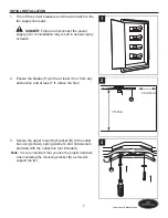
Page 7: ...injury or death 1 2 Ensure the blades H will be at least 30 in from any obstruction and at least 7 ft above the floor H 2 7 ft Min 30 in Min 3 Secure the upper mounting bracket B to the outlet box us...

Page 8: ...ket M into a slot in the upper mounting bracket B Then slide the second lower mounting bracket M tab into the second slot on the upper mounting bracket B until all four holes are in alignment B M 6 Re...

Page 9: ...and Blue wires from the fan to the Black wire from the ceiling Connect the White wire from the fan to the White wire from the ceiling Connect all Ground Green wires together from the fan to the Bare G...

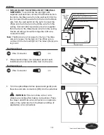
Page 10: ...r for the fan The Blue wire is hot power for the light kit The White wire is common for the fan and light kit The Green Bare wire is ground Hardware Used DD Wire Connector x 4 WHITE WHITE BLACK WALL S...

Page 11: ...ng Screw x 4 B A HH HH 1 2 Slide the motor housing A over the motor D aligning the slotted holes in the motor housing A with the loosened motor housing screws HH in the mounting bracket B Twist the mo...

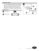
Page 12: ...one blade isolator GG to attach the blade arm G to the motor D Tighten the motor screws AA securely Repeat this step for the remaining blade arms G making sure to completely secure each blade arm G b...

Page 13: ...housing L matching the colors on each plug Ensure the plugs connect tightly Hardware Used II Fitter Plate Screw x 3 D D L II 1 2 Align the holes in the switch housing L with the holes on the fitter p...

Page 14: ...ex nut FF finial plate J and finial K Take care to align the holes on the glass shade F so that the pull chains can pass through and move freely Hardware Used FF Hex Nut x 1 JJ Flat Washer x 1 F L FF...

Page 15: ...it E Carefully place unused wires back into the switch housing L and use the plastic plug button C to plug the hole Then re install the plate screws II and secure with a Phillips screwdriver Hardware...

Page 16: ...1 The pull chain located on the switch housing L has four positions to control fan speed One pull is HIGH two is MEDIUM three is LOW and four turns the fan OFF L 1 2 The pull chain located in the cent...

Page 17: ...move stagnant hot air off the ceiling area The reverse switch must be set either completely left or completely right in or der for the fan to function correctly If the reverse switch is set in the mi...

Page 18: ...ange dimmer switch to control the fan speed 4 Run the fan continuously for 24 48 hours on medium or high speed for a break in period 5 Ensure the outlet box is secured to the building structure 6 Ensu...

Page 19: ...to varying climate conditions this warranty does not cover any changes in brass finish including rusting pitting corroding tarnishing or peeling Brass finishes of this type give their longest useful...

Page 20: ...m 5 p m EST Friday PART DESCRIPTION PART A Motor Housing 403520 A B Mounting Bracket 403520 B C Plastic Plug Button 403520 C F Glass Shade 403520 F G Blade Arm 403520 G H Blade 403520 H J Finial Plat...

Page 21: ...ves de 8 a m a 6 p m y los viernes de 8 a m a 5 p m hora est ndar del Este 21 ADJUNTE SU RECIBO AQU N mero de serie _________________________ Fecha de compra _________________________ Lowes com harbor...

Page 22: ...i n de seguridad 25 Preparaci n 26 Instalaci n inicial 27 Cableado 29 Instalaci n final 31 Instalaci n del kit de iluminaci n 32 Instrucciones de funcionamiento 36 Cuidado y mantenimiento 37 Soluci n...

Page 23: ...motor 1 E Ensamble del kit de iluminaci n preensamblado en la carcasa del interruptor L 1 F Pantalla de vidrio 1 G Brazo del aspa 5 H Aspa 5 I Bombilla 3 J Placa del remate preensamblada en el soport...

Page 24: ...M Tuerca hexagonal Cant 1 preensamblada en el ensamble del kit de iluminaci n E Aislador de aspa Cant 5 Tornillo de montaje de la carcasa del motor Cant 4 preensamblado en la abrazadera de montaje sup...

Page 25: ...olar la velocidad del ventilador ADVERTENCIA Para reducir el riesgo de incendios descargas el ctricas o lesiones personales instale el ventilador en una caja de salida marcada como APTA PARA SOSTENER...

Page 26: ...de tener todas las piezas Compare todas las piezas con la lista del contenido del paquete y con la lista de aditamentos No intente ensamblar el producto si falta alguna pieza o si estas est n da adas...

Page 27: ...ves o la muerte 1 2 Aseg rese de que las aspas H est n al menos a 76 20 cm de cualquier obstrucci n y al menos a 2 13 m del piso H 2 2 13 m min 76 cm min 3 Asegure la abrazadera superior de montaje B...

Page 28: ...azadera superior de montaje B Luego desplace la segunda leng eta de la abrazadera inferior de montaje M en la segunda ranura de la abrazadera superior de montaje B hasta que los cuatro orificios est n...

Page 29: ...O Conecte los conductores negro y azul del ventilador al conductor negro del techo Conecte el cable blanco del ventilador al cable blanco del techo Conecte todos los cables de tierra verdes juntos des...

Page 30: ...el cable com n para el ventilador y el kit de iluminaci n El cable verde desnudo es de tierra Aditamentos utilizados DD Conector de cables x 4 BLANCO BLANCO NEGRO INTERRUPTOR DE PARED NEGRO NEGRO INTE...

Page 31: ...Desplace la carcasa del motor A sobre el ensamblaje del motor D alineando los orificios ranurados de la carcasa del motor A con los tornillos de montaje de la carcasa del motor aflojados HH en la abr...

Page 32: ...or x 10 Aislador de aspa x 5 D AA H G 4 GG INSTALACI N DEL KIT DE ILUMINACI N Nota Si desea instalar el ventilador sin el kit de iluminaci n consulte la secci n C mo instalar el ventilador sin el kit...

Page 33: ...itamentos utilizados II Tornillo de la placa de soporte x 3 L D II 2 3 Instale las bombillas I en los portal mparas de la carcasa del interruptor L Importante Aseg rese de que las bombillas I y el kit...

Page 34: ...as de tiro puedan pasar por los orificios y moverse libremente Aditamentos utilizados FF Tuerca hexagonal x 1 JJ Arandela plana x 1 F L FF 5 K J JJ 6 Conecte las extensiones para la cadena de tiro KK...

Page 35: ...ilizaron nuevamente en la carcasa del interruptor L y utilice el bot n de tap n pl stico C para tapar el orificio Luego vuelva a instalar los tornillos de la placa II y aseg relos con un destornillado...

Page 36: ...or L tiene cuatro posiciones para controlar la velocidad del ventilador Jale una vez para la posici n ALTA dos para la posici n MEDIA tres para la posici n BAJA y cuatro para la posici n APAGADO la qu...

Page 37: ...mover el aire caliente estancado fuera del rea del techo El interruptor de reversa se debe deslizar completamente hacia la izquierda o completamente hacia la derecha para que el ventilador funcione co...

Page 38: ...la velocidad del ventilador 4 Haga funcionar el ventilador de 24 a 48 horas continuamente a velocidad media o alta durante el per odo de asentamiento 5 Revise que la caja de salida est asegurada a la...

Page 39: ...la garant a Debido a las cambiantes condiciones clim ticas esta garant a no cubre cambios en el acabado de lat n incluidos la oxidaci n las picaduras la corrosi n el deslustre o el descascarado Los ac...

Page 40: ...a 5 p m hora est ndar del Este PIEZA DESCRIPCI N PIEZA A Carcasa del motor 403520 A B Soporte de montaje 403520 B C Bot n de tap n pl stico 403520 C F Pantalla de vidrio 403520 F G Brazo del aspa 403...

Reviews: