background image

Scissor  lift                                                                


      Happ10


 Version 4.0 

©HAPP Australia Pty Ltd 

Page 23 


Chapter   7   Maintenance      


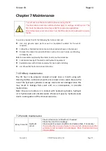
Turn  off  and  lock  the  main  switch  before  servicing  the  lift.  


The  maintenance  intervals  indicated  below  apply  to  average  workshop  use.  The  
lift  should  be  inspected  more  frequently  for  severe  use  applications.  


Only  trained  personnel  who  knows  how  the  lift  works  must  be  allowed  to  service  
the  lift.


To   service   properly   the   lift,   the   following   has   to   be   carried   out:   


l


Use    only    genuine    spare    parts    as    well    as    equipment    suitable    for    the    work   
required;   


l


Follow   the   scheduled   maintenance   and   check   periods   shown   in   the   manual;   


l


Discover   the   reason   for   possible   failures   such   as   too   much   noise,   overheating,   
oil   blow-­‐by,   etc.   


Refer   to   documents   supplied   by   the   dealer   to   carry   out   maintenance:   


l


Functional   drawing   of   the   electric   and   hydraulic   equipment      


l


Exploded   views   with   all   data   necessary   for   spare   parts   ordering   


l


List   of   possible   faults   and   relevant   solutions.   


7.1   Ordinary   maintenance      

The    lift    has    to    be    properly    cleaned    at    least    once    a    month    using    self-­‐

cleaning   clothes.   Lubricate   all   pivot   pins   at   least   once   a   week.   Be   sure   the   
rod   of   the   hydraulic   cylinders   is   always   clean   and   not   damaged   since   this   
may    result    in    leakage    from    seals    and,    as    a    consequence,    in    possible   
malfunctions.      

Note:   Ensure   no   moisture   is   in   contact   with   hydraulic   cylinders,   hydraulic   

oil    is    hydroscopic    and    absorbs    water.    Water    will    pass    by    hydraulic    seals   
due   to   sucking   action   of   the   internal   ram   tube.


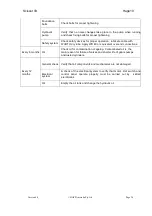
7.2   Periodic   maintenance      

Every  3  months


Hydraulic  
circuit  


Check  oil  tank  level;;  refill  with  oil,  if  needed;;  


Check  the  circuit  for  oil  leakage.      


Check  seals  for  proper  conditions  and  replace  them,  if  necessary;;


If  oil  is  milky  this  is  a  sign  of  water  in  the  oil  which  will  soon  cause  the  
cylinders  to  rust  and  seals  to  be  damaged.    Drain,  Flush  and  add  new  
oil  immediately.  


Summary of Contents for Happ10

Page 1: ...RTANT SAFETY INSTRUCTIONS SAVE THESE INSTRUCTIONS PLEASE READ THE ENTIRE CONTENTS OF THIS MANUAL PRIOR TO INSTALLATION AND OPERATION BY PROCEEDING WITH LIFT INSTALLATION AND OPERATION YOU AGREE THAT Y...

Page 2: ...ty device 7 3 3 Risk list 8 3 4 Warning labels 9 Chapter 4 Installation 10 4 1 Tools required 10 4 2 Selecting a site 10 4 3 Floor requirements 10 4 3 Installation steps 11 Chapter 5 Adjustment 19 5 1...

Page 3: ...e loading and unloading operation goods must be handled by vehicles or ships At the arrival of the goods verify that all items specified in the delivery notes are included and undamaged If you find mi...

Page 4: ...asy operation and mechanical safety protection It is especially suitable for high precision wheel alignment and Auto s repair and maintenance The features as below 1 The minimum height is 230mm at gro...

Page 5: ...ures of item and text description to admin happ com au with claim details we will advise if parts need to be sent to us In order to advise production of a fault or defect we must supply pictures and t...

Page 6: ...nded 2 5 Technical parameters Model type HAPP10 Capacity 2700kg Max lifting height 1400mm Platform length 1800mm Platform width 1000mm Lifting time 50s Descent time 35s Whole machine length 2550mm Who...

Page 7: ...safety devices are off line People the lift and the vehicles lifted can be seriously damaged if these instructions are not followed 3 1 General warnings The operator and the person in charge of maint...

Page 8: ...lift is stopped at relatively low elevations personnel must be careful to avoid impact with parts of the machine not marked with special colours Risk of vehicle moving Cause by operations involving th...

Page 9: ...riate materials and construction techniques in relation to the specified use of the machine in order to manufacture a reliable and safe lift Note however that the lift must be used in conformity with...

Page 10: ...roduct warranty Manufacturer will assume no liability for loss or damage of any kind expressed or implied resulting from improper installation or use of this product Please read entire manual prior to...

Page 11: ...s from packaging Typically the system ships with three packages Pump assembly Hoist Trolley Unpack the items and confirm parts are there for attachment which include Bolts nuts for attaching pump asse...

Page 12: ...mbly The pump unit is fitted to multiple models the outlet hose can be installed on either side of the control block by swapping the pipe joint for the plug screw on the other side Confirm fittings ar...

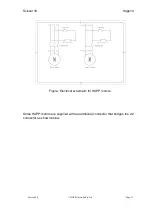
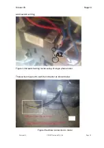
Page 13: ...or lift Happ10 Version 4 0 HAPP Australia Pty Ltd Page 13 Figure Electrical schematic for HAPP motors Some HAPP motors are supplied with an additional connector that bridges the A2 connector as shown...

Page 14: ...Version 4 0 HAPP Australia Pty Ltd Page 14 Limit switch wiring Figure Limit switch wiring inside wiring of single phase motor These wires map out to a white connector as shown below Figure Electrical...

Page 15: ...lia Pty Ltd Page 15 This white connector is used to attach a limit switch to the hoist In cases where this connector is not required bridge connect these two wires and insulate to disable the connecto...

Page 16: ...ither shielded with extra insulation or moved back inside the control box If the limit switch is operational the 4Amp fusible link must be installed and the 3 core cable connected to the limit switch...

Page 17: ...lley handle Unfortunately no commercial shims are available at this point To make the lever mount firm place a small piece of rubber in between the lever mount and the trolley bar to facilitate tighte...

Page 18: ...ty ratchet bar If lever is released the latch will engage If the latch is not engaging correctly adjust the cable tension at either end of cable to achieve consistent operation Car lift test Position...

Page 19: ...lift reaches full height Damage to the motor can occur if continued l Cylinders may jump upon initial start up which is normal due to trapped air inside the hydraulic lines If the lift cannot be raise...

Page 20: ...ck with load WARNING Please follow carefully the instructions in the coming paragraph for avoiding damages on the lift Carry out two or three complete cycles of lowering and lifting and check Repeat t...

Page 21: ...efly stop and check adapters for secure contact Make sure the vehicle doors are closed during raising and lowering cycles In case of defects or malfunctions such as jerky lift movement or deformation...

Page 22: ...ensure that the lift rests on the safety before any attempt is made to work on or near the vehicle Depress lower lever on pump assembly to lower onto safety latch Inspect safety latch to verify latch...

Page 23: ...aulic equipment l Exploded views with all data necessary for spare parts ordering l List of possible faults and relevant solutions 7 1 Ordinary maintenance The lift has to be properly cleaned at least...

Page 24: ...lube Apply WD 40 or equivalent over end connections Every 6 months Oil Check oil for contamination or ageing Contaminated oil is the main reason for failure of valves and shorter life of gears pumps...

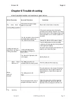
Page 25: ...verse Change the phases of the power supply Lifting with light load is normal ebut no lifting with heavy load o The set safe pressure of the over flow valve may be increased by turning the set knob ri...

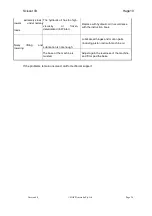
Page 26: ...d in Winter Replace with hydraulic oil in accordance with the instruction book Noisy lowering lifting and Lubrication is not enough Lubricate all hinges and motion parts including piston rod with mach...

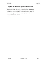
Page 27: ...and Disposal of used oil Use a hydraulic oil with a viscosity of 46 Used oil which is removed from the power unit and the plant during an oil change must be treated as a polluting product in accordanc...

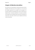
Page 28: ...ped as iron In any case all the materials deriving from the demolition must be disposed of in accordance with the current standards of the country in which the rack is installed Finally it should be r...

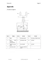
Page 29: ...ppendix 1 Hydraulic diagram Item Name Item Name Item Name 1 Filter 5 One way valve 9 One way throttle valve 2 Gear pump one way throttle valve 6 Unloading valve 10 cylinder 3 Motor one way valve 7 Flo...

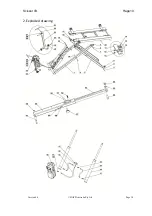
Page 30: ...Scissor lift Happ10 Version 4 0 HAPP Australia Pty Ltd Page 30 2 Exploded drawing...

Page 31: ...are manufactured at the highest standard the installation and operating procedures for any equipment are the responsibility of the owner of the hoist Lift installation and operating conditions can si...

Reviews: