background image

Multi Loop Controller

50

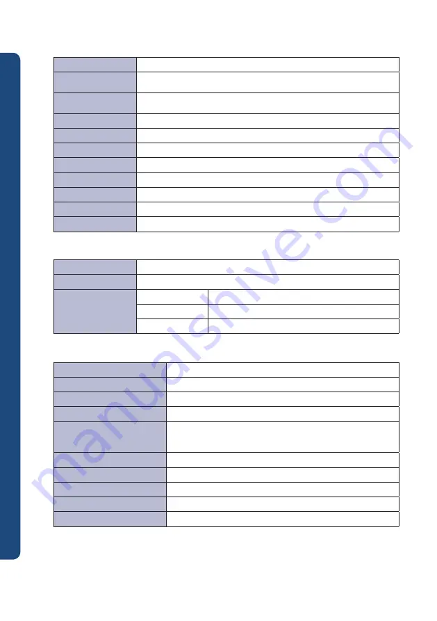
▶ RS485 communication

Communication method

RS-485 EIA standard / 2 line type semi-double

Maximum number of 

access

31 units

Maximum communication 

distance

1200 m

Communication sequence No sequence

Communication speed

9600, 19200, 38400, 76800 bps [initial value: 9600]

Start bit

1 bit

Data length

7, 8 bit [initial value: 8]

Parity bit

None, Odd, Even [initial value: Even]]

Stop bit

1, 2 bit [initial value: 1]

Response time

Reception handling time + (response time x 10 ms)

Support protocol

PC-Link, PC-Link with SUM, Modbus ASCII/RTU [initial value: PC-Link]

Power source voltage

24 V d.c.

Voltage regulation

±10% of power source voltage

Power consumption

Maximum 7W below

ML-D4S/C, ML-D2HMS/SS

Maximum 5W below

ML-D4M, ML-D2HMM

Maximum 3W below

ML-E

▶ Power source specification

Usage surroundings temperature

0 ~ 50 ℃

Usage surroundings humidity

35 ~ 85% RH (however, there should not be condensation)

Run environment

Should not be areas with toxic gas, magnetic field or dust

Warming up time

Minimum 30 minutes

Influence by surrounding 

temperature

Thermo couple, direct current voltage: Larger side between ±3 uV / 
oC or ±0.03% of FS / oC
Thermo-resistor: Below ±0.1oC / oC

Influence by power supply change

Larger side between ±3 uV / 10 V or ±0.03% of FS / 10 V

Storage temperature

-25 ~ 65 ℃

Storage humidity

5 ~ 95% RH (however, there should not be condensation)

Shock

Less than 1 m in packaged condition

Weight

About 220g (excluding box)

▶ General specification

Summary of Contents for ML-D2H

Page 1: ......

Page 2: ...anual contact our company or business offices Unpermitted reprinting and duplication of all or part of contents of this manual are strictly prohibited Services A S For A S request of this company s pr...

Page 3: ...5 RS232C 9 2 5 Event output unit connections 11 3 1 Protocol composition 12 3 2 Register composition 18 3 2 1 ML D2H register composition 18 3 2 2 ML D2H register description 20 3 2 3 ML D4 register c...

Page 4: ...ck at front part and only connected unit is communicated regardless of front side switch setup It is for unit s initial setting Input type Thermocouple 12 types K J E T R B S L N U W PL2 RTD 2 types P...

Page 5: ...A d c parameter optional output OUT2 cooling Relay output SS OUT1 heating SSR SCR 4 20 mA d c parameter optional output OUT2 cooling Module type temperature controller ML D2H Ex Temperature control sy...

Page 6: ...damage is caused to user or third party due to defects and inevitable accidents that are impossible to predict by this company the company on any occasion will not be responsible for loss indirect da...

Page 7: ...truments before start of wiring work This product operates at DC24 V There is danger of electric shocks and fire if other than rated power supply is used To use ML Series as one module by connecting s...

Page 8: ...source and communications termina RS485 communications and 24 V d c input terminal If unit extension address switch is positioned at 16 and unit address switch is positioned at 1 RS485 communications...

Page 9: ...rent is not flowing through connection cable by cutting off voltage to all instruments to be supplied with power As there is danger of electric shock while current is flowing make sure not to touch te...

Page 10: ...4 5 6 7 8 9 10 11 12 13 14 15 16 17 18 19 20 21 22 23 24 24 V d c terminal has no polarity of for power supply connection ML E Power supply section 2 3 Exterior dimension Unit 87 00 96 90 9 90 1 50 1...

Page 11: ...ed automatically during module composition Dotted line is connected automatically during module composition 4 wire type communication and power source connection Example of proper use Example of incor...

Page 12: ...ontrol and monitoring of connected unit is possible 2 4 3 RS485 communication Individual control is also possible using RS485 communication with unit address set as Unit Address switch Unit address se...

Page 13: ...ition Mamimum 32 units Max 31 if ML E not included RS485 ML E ML E can be located and connected anywhere during module composition ML E ML E When making up as one module only 1 unit should be connecte...

Page 14: ...ng communication Command STX Address Command Data CR LF STX 01 99 Refer to each Command 0x0D 0x0A Command Detail D R S D Register consecutive reading D R R D Register random reading D W S D Register c...

Page 15: ...Byte size 1 2 3 1 2 1 4 1 4 1 1 4 1 1 Description STX Address DWS EA D Register Data 1 Data n CR LF Reception frame Data Hexadecimal number Word data string Byte size 1 2 3 1 2 1 4 1 1 4 1 1 Descript...

Page 16: ...0x03 Number Number of communications and number of Data do not match 0x04 Data Data is out of Hex 0x0 0xF 0x08 Delim Terminating string CR LF error 0x10 SUM Inconsistent SUM value 0x18 Over range Valu...

Page 17: ...7 Frame confirmation CRC low 8 bit XX h 8 Frame confirmation CRC high 8 bit XX h 9 Frame terminating character None Serial number Details Size Ex 0 Frame head character None 1 Device number 8 bit 01...

Page 18: ...a high 8 bit 12 h 6 Transmission data high 8 bit 34 h 7 Frame confirmation CRC low 8 bit XX h 8 Frame confirmation CRC high 8 bit XX h 9 Frame terminating character None Serial number Details Size Ex...

Page 19: ...h 8 Data to record 1 high 8 bit dd h 9 Data to record 1 low 8 bit dd h n 4 Data to record n high 8 bit dd h n 3 Data to record n low 8 bit dd h n 2 Frame confirmation CRC low 8 bit XX h n 1 Frame conf...

Page 20: ...L 1 EV 1VL 2 23 EV 1HY 1 EV 1HY 2 24 EV 2TY 1 EV 2TY 2 Event channel 2 setting 25 EV 2VL 1 EV 2VL 2 26 EVT_STS Event status EV 2HY 1 EV 2HY 2 27 EVBUS_STS Event output status EV 3TY 1 EV 3TY 2 Event c...

Page 21: ...tus by event OLL 1 OLL 2 Auto tuning hysteresis 67 EV 2STS AT_HYS 1 AT_HYS 2 Auto tuning hysteresis 68 EV 3STS 69 EV 4STS 70 EV 5STS 71 EV 6STS BS 1 BS 2 Input compensation 72 EV 7STS FL 1 FL 2 Input...

Page 22: ...ously set 0 no event occurred 1 event occurred ABS 27 1B EVBUS_STS Event Bus output status R Event bus output OR run 7 Bit 128 Set 1 at event bus8 output occurrence 6 Bit 64 Set 1 at event bus 7 outpu...

Page 23: ...channel 1 4 status R 70 46 EV 5STS Event channel 5 channel 1 4 status R 71 47 EV 6STS Event channel 6 channel 1 4 status R 72 48 EV 7STS Event channel 7 channel 1 4 status R 73 49 EV 8STS Event channe...

Page 24: ...t 1 at event channel 6 occurrence 4 Bit 16 Set 1 at event channel 5 occurrence 3 Bit 8 Set 1 at event channel 4 occurrence 2 Bit 4 Set 1 at event channel 3 occurrence 1 Bit 2 Set 1 at event channel 2...

Page 25: ...0 100 EUS 100 147 93 247 F7 EVSTOP Set stop run at event occurrence R W 0 continuous run 1 stop run ABS 0 continuous run 148 94 248 F8 HBC Heater break current value R 1 50A A 149 95 249 F9 HBA Heate...

Page 26: ...Set scale high limit at DCV input setting R W EU 0 100 mV EU 100 178 B2 278 116 SLL Set scale low limit at DCV input setting R W EU 0 100 mV EU 0 179 B3 279 117 DOT Set decimal point R W 0 3 decimal p...

Page 27: ...2 EV 8DLY 3 EV 8DLY 4 Event 8 delay setting 21 TSV 1 Current target set value EV 1TY 1 EV 1TY 2 EV 1TY 3 EV 1TY 4 Event 1 setting 22 TSV 2 EV 1VL 1 EV 1VL 2 EV 1VL 3 EV 1VL 4 23 TSV 3 EV 1HY 1 EV 1HY...

Page 28: ...g temperature 62 EVSTS 2 RMIN 1 RMIN 2 RMIN 3 RMIN 4 SV increase and decrease time minute 63 EVSTS 3 RHRS 1 RHRS 2 RHRS 3 RHRS 4 SV increase and decrease time hour 64 EVSTS 4 DR 1 DR 2 DR 3 DR 4 Contr...

Page 29: ...of auto toning AT 10 Bit Set 1 at standard contact point correction RCJ error 9 Bit Set 1 when exceeding 5 input range 8 Bit Set 1 at input sensor error B OUT 2 Bit Set 1 at auto tuning AT run 1 Bit S...

Page 30: ...t 8 Set 1 at event channel 4 occurrence 2 Bit 4 Set 1 at event channel 3 occurrence 1 Bit 2 Set 1 at event channel 2 occurrence 0 Bit 1 Set 1 at event channel 1 occurrence ABS 66 42 EV 1STS Event chan...

Page 31: ...302 12E 402 192 SV Set value R W EU 0 100 EU 0 103 67 203 CB 303 12F 403 193 MV Manipulated Value R 0 0 100 0 0 104 68 204 CC 304 130 404 194 CHSTS Channel status R All error status OR run 15 Bit Set...

Page 32: ...igh limit stand by 6 Deviation low limit stand by 7 Deviation low high limit stand by 8 Within deviation stand by 9 PV high limit 10 PV low limit 11 PV high limit stand by 12 PV low limit stand by 13...

Page 33: ...inute 0 163 A3 263 107 363 16B 463 1CF RHRS Set SV change time hr at RAMP control R W 0 100 Hour 0 164 A4 264 108 364 172 464 1D0 DR Set control run R W 0 Reverse run heating control 1 Forward run coo...

Page 34: ...t When using 4 20mA direct current input please select input code 31 and attach 250 of electric resistance to both input terminals 3 3 Manipulation and run 3 3 1 Input section Input type INP It is a p...

Page 35: ...t range OVER of alarm group 1 of CHESTS channel status is occurs The control is operating normally Input scale range high SLH scale range low SLL setting It applies only if input type is set to voltag...

Page 36: ...hen run setting R S is run stop Stop mode Control run X Even occurrence X Control run X Even occurrence X Monitor mode Control run X Even occurrence O Control run X Even occurrence O Run mode Control...

Page 37: ...FF control OUT 100 0 DEAD BAND ON OFF OUTPUT 0 0 DEAD BAND 100 100 OUTPUT 0 0 100 100 When heating and cooling sides are PID control and dead band as much set value Heating Cooling are PID control and...

Page 38: ...f auto tuning AT is performed Auto tuning AT Normally for 2 DOF P I D control Values of P I D constants such as proportional band PB integral time TI differential time TD should be set to targeted tem...

Page 39: ...rbance can be obtained Alpha AP parameter set value SV is used for adjusting response feature to set value SV ON Relay run ON ON OFF MV 30 3S Control cycle CT 10 sec Control cycle CT 10 sec Control cy...

Page 40: ...d control output capacity can be set at RO parameter Manipulated Value MV high limit OHL low limit OLL Controlled manipulated value can be limited by high limit value OHL and low limit value OLL Manua...

Page 41: ...transit time hour Set value that changes based on time can be verified with current target set value TSV parameter Upon executing auto tuning AT ramp function stops and auto tuning is performed using...

Page 42: ...by event channel If event occurs only with event channel that EVBUS 1 8 parameter is set to 1 event bus is used for output If one module is made up with several units combined event bus output occurs...

Page 43: ...Event type Event type Stand by have not have 10 PV low limit X 11 PV high limit O 12 PV low limit O 13 SV high limit X 14 SV low limit X 15 Lo op break alarm LBA X 16 17 Run X 18 Stop monitor Ready X...

Page 44: ...e above types If event type EVTY is changed event set value EVVL and event hysteresis EVHY are initialized If process value PV is out of pre set event value EVVL event occurs and for release it should...

Page 45: ...BT loop break alarm LBA occurs Loop break alarm occurs only if manipulated Value MV is 100 or 0 If process value PV is within the range of proportional band PB and if loop break dead band LBD paramete...

Page 46: ...mode and run setting R S is run start event occurs Stop monitor READY state event If channel mode CHMD is monitor mode or run mode and run setting R S is run stop event occurs FAIL state indication ev...

Page 47: ...em Data error 32768 Warning group 2 Bit 15 CALIB Calibration Data error 16384 Bit 14 ADC Input circuit error 8192 Bit 13 EEPROM EEPROM error 4096 Bit 12 ATE Auto tuning does not terminate within 24 ho...

Page 48: ...e DOSTS Indicate event bus output state Event output can occur only if event occurs in event channel corresponding channel at event bus output EVBUS parameter is set to 1 and output state can be chang...

Page 49: ...cessed as follows 3 3 5 Warning occurrence and handling Type Cause Process value PV display Manipulated Value MV state B OUT Input sensor error Reverse run 105 forward run 5 PO output after closing co...

Page 50: ...Allowed input voltage Within 2 5 Thermo couple thermo resistor within 5 12 V direct current Input correction 100 of input range Cold junction compensation error 1 5 0 50 Input signal break detection u...

Page 51: ...00 of FS Integral time 0 3 600 sec Differential time 0 3 600 sec Proportional cycle About 25 30 seconds relay control output 2 4 seconds voltage pulse SSR control output ON OFF control Set proportiona...

Page 52: ...of power source voltage Power consumption Maximum 7W below ML D4S C ML D2HMS SS Maximum 5W below ML D4M ML D2HMM Maximum 3W below ML E Power source specification Usage surroundings temperature 0 50 Us...

Page 53: ...limit 15 Loop break alarm LBA 16 Heater break alarm HBA 17 Run start RUN 18 Run monitor mode READY 19 FAIL 0 None OFF 1 Deviation high limit 2 Deviation low limit 3 Deviation high low limit 4 Within...

Page 54: ...MA0616E170320 ML series HANYOUNG NUX CO LTD 28 Gilpa ro 71 beon gil Nam gu Incheon Korea Tel 82 32 876 4697 Fax 82 32 876 4696 E mail overseas hynux com...

Reviews: