Hanwell Smart Receiver 2 (SR2)
Instruction Manual
hanwell.com
Page 15 of 22
IM6001 - 3
6.2
MS1000 Control Panel
The SR2 can be connected to a
Hanwell MS1000 Control Interface
. See the Online User
Guide:
http://www.help.emsprocloud.com/index.html?bms-control.html
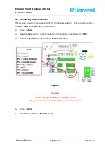
The MS1000 Unit should be connected to JP12 (See
Appendix 1 – SR2 Connection Data
) as
follows:
Pin Connection
1 12V
OUT
2 TX
+
3 TX
-
4 GND
6.3
On Board Sensors
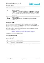
The SR2 has 8 inputs for local probes, the equivalent of 4 x RL2000 Sensors with pre-defined
ID numbers.
The probes should be connected to JP13 (See Appendix 1 – SR2 Connection Data), as follows:
Radio Sensor Type
EMS ID No.
Channel
Probe Connections
RL2000 Dual
Thermistor
200
Thermistor A
Pin 1: positive
Pin 2: GND
Thermistor B
Pin 3: positive
Pin 4: GND
RL2000
RH/Thermistor
201
RH
Pin 5: +5V
Pin 6: signal
Pin 8:GND
Thermistor
Pin 7: positive
Pin8: GND
RL2000 Linear
202
Linear
4 to 20mA
Pin 9: positive
Pin 10: negative
Linear
4 to 20mA
Pin 11: positive
Pin 12: negative
RL2000 203
Digital
Pin 13: positive
Pin 14: negative
Digital
Pin 15: positive
Pin 16: negative
Summary of Contents for IM6001
Page 1: ...hanwell com IM6001 Hanwell Smart Receiver 2 SR2 User Manual ...
Page 2: ...Intentionally Blank ...
Page 25: ......

