Hanwell Smart Receiver 2 (SR2)
Instruction Manual
IM6001 - 3
Page 12 of 22
hanwell.com
5
Advanced SR2 Configuration
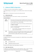
The SR2 is sent out set to its Default Hardware Configuration.
These Default settings can be changed via a set of 8 DIP switches on the back of the display
PCB.
Note:
Switches 5 - 8 inclusive are not used and should be set to OFF.
5.1
Fall Back Operation
Defines the SR2’s behaviour in the event of a network or mains power failure.
Set with DIP Switch 1:
ON
(Default)
In the event of mains power failure, the SR2 will switch to Power-Fail
mode. The Receiver will only be powered up for 5 minutes in every 10
to prolong the life of the on-board battery.
In the event of no network Comms for 75 minutes, the SR2 will switch
to
Comms – Fail mode
.
In either case the SR2 will log the first signal received from each
sensor in a 10 minute period.
This will greatly increase the time before which wraparound
starts to overwrite older data.
OFF
In the event of a Comms or mains power failure, the SR2 continues to log all
data received while power is available. If Comms is not restored when the
memory becomes full, older data will start to be overwritten.
5.2
On-Board Sensors
The SR2 has 8 inputs for local probes, the equivalent of 4 x RL2000 Sensors with pre-defined
ID Numbers.
Set with DIP Switch 2:
ON
The inputs are read
OFF
(Default) The inputs are not read
See Section 6.3 for details of the On-Board Sensor connections.
5.3
Alarm Relay Operation
The SR2 has an on-board 12V relay which can be connected to a buzzer or beacon. The relay
is normally held closed. It opens in the event of any alarm on the assigned Grids.
Summary of Contents for IM6001
Page 1: ...hanwell com IM6001 Hanwell Smart Receiver 2 SR2 User Manual ...
Page 2: ...Intentionally Blank ...
Page 25: ......


