User Manual 48
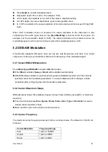
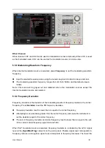
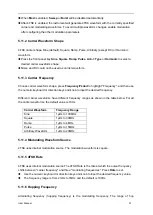
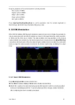
The frequency range is from 2mHz to 1MHz and the default is 100Hz.
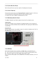
5.8.6 Modulating Phase
Press
Phase
to set the parameter.
Use the numeric keyboard or direction keys and knob to input the desired amplitude value.
The phase range is from 0º to 360º and the default is 180º.
5.9 QPSK Modulation
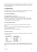
You can configure the instrument to "shift" its output phase between four preset values using
QPSK modulation. The rate at which the output shifts between the four phases (called the "carrier
phase" and three "modulation phases") is determined by the internal signal level of the instrument.
5.9.1 Select QPSK Modulation
Press
Mod->Type->QPSK
to enable this function.
When
Mod
is enabled,
Sweep
or
Burst
will be disabled automatically.
After QPSK is enabled, the instrument will generate QPSK waveform with the currently
specified carrier and modulating waveforms. To avoid multiple waveform changes, enable
modulation after configuring the other modulation parameters.
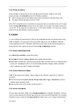
5.9.2 Carrier Waveform Shape
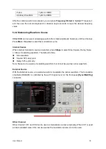
QPSK carrier shape: Sine (default), Square, Ramp, Pulse, Arbitrary (except DC) or Harmonic
waveform.
Press the front panel key
Sine
,
Square
,
Ramp
,
Pulse
,
Arb -> Type
or
Harmonic
to select a
desired carrier waveform shape.
Noise and DC could not be used as carrier waveform.
5.9.3 Carrier Phase
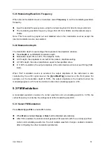
Choose carrier waveform shape, press
Phase
to highlight "Phase", and then use the numeric
keyboard or direction keys and knob to input the desired phase. The available phase ranges from
0º to 360º and the default value is 0º.
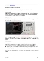
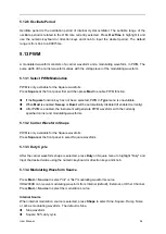
5.9.4 Modulating Waveform Source
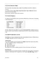
QPSK uses internal modulation source. Press
Data Source
softkey, and select PN15 and PN21
codes as the modulation source. The default data source is PN15 code.

