


10
CONNECT
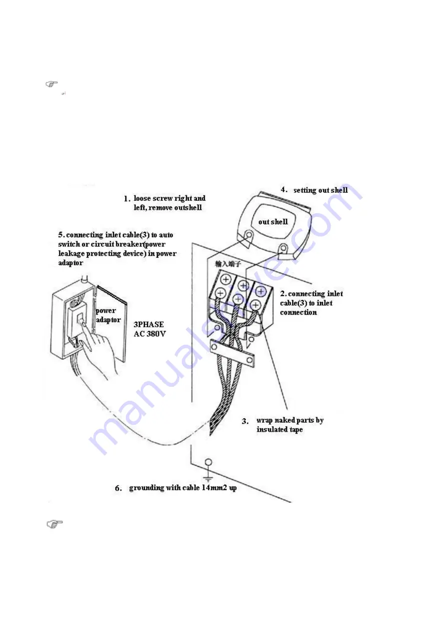
Connection and Grounding
Safety warning
Avoiding accidents happen such as electric shock,burning etc, follow rule should be
abided by:
●
Connecting power cable should be under”power off”, and absolutely safety
condition.
●
Don’t touch any parts with damp hands.
Attention
Avoiding fire, burn machine or unstable arc occurred by cable over-heated:
●
cable should be more than demaned specification
●
don’t hang any things on cable or touch welding parts
Summary of Contents for FKR350
Page 8: ...7 5 PARTS NAME AND FUNCTION welding power operation front panel...
Page 9: ...8 Welding power...
Page 10: ...9 remote controller...
Page 17: ...16 Preparation before welding operation Install wire...
Page 25: ...24 wire fed machine gas flow meter...
Page 27: ...26 Dimension diagram FKR350 unit mm FKR500 unit mm...
Page 29: ...28...
Page 34: ...33 Daily overhaul continual...
Page 35: ...34 Daily overhaul continua...
Page 36: ...35...
Page 42: ...41...
Page 43: ...42...
Page 44: ...43...
Page 47: ...46 5 Circuit diagram...


