


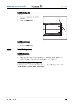


Procedure
1. Align the gear unit (A) with the
machine shaft (B). Make sure that
the keyways of the machine shaft
and the hollow shaft align.
2. Move the gear unit until the
installation key (C) and the
installation disk (D) touch each
other. Use the threaded rod (E), the
nut (F) and the installation disk.
3. Remove these parts:
• threaded rod
• nut
• installation disk
• installation key
Do a check on the final key
Procedure
1. Measure the clearance between the final key and the keyway of the hollow shaft.
2. Compare the clearance with the specification. Refer to the certified drawing.
3. If the clearance is not correct, use a new final key.
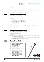
Install the final key
Caution: Make sure that there is no opening between the parts (F), (G) and
(H). If there is an opening, water can come in an cause corrosion.
Procedure
1. Install the final key (A) in the
keyway (B).
2. Install the installation disk (C), the
nut (D) and the threaded rod (I).
3. Move the gear unit (E) until the
surfaces (F) and (G) firmly touch
each other. Use the threaded rod
(I), the nut and the installation disk.
4. Remove the threaded rod, the nut
and the installation disk that are
used for installation.
B
C
F
D
E
A
H
F
A
B
D
C
I
E
G
Installation
36
IM_405_002_EN


