12
Step 7
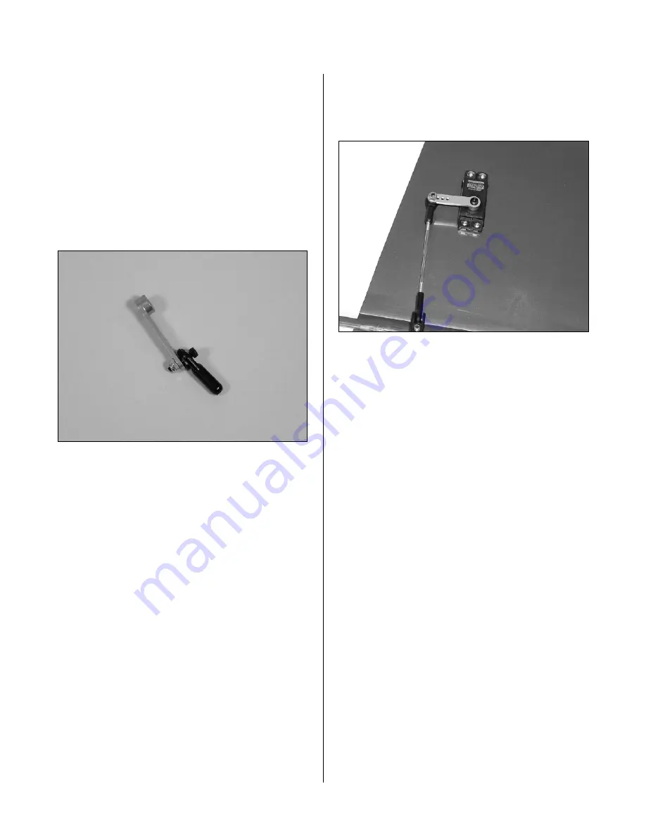
Using the 4-40 screws (don’t substitute a standard
screw) and nuts included, attach the ball link to
the outer hole in the servo arm from the bottom
side as shown. The sequence is screw, ball link,
servo arm and nut. Don’t forget to use threadlock.
Note
: Hangar 9® aluminum servo arms
are suggested for ease of installation and
durability. Use 3D 1/2 Servo Arm 4-40: JR
(HAN3578) for the aileron servos.
Step 8
Screw a 4-40 ball link 5 to 6 turns onto each end of
a 3
1
/
2
" long aileron linkage. Adjust the linkage length
until the hole in the ball link aligns with the outer
hole in the servo arm when the aileron is neutral and
the servo arm is centered.
Step 9
Center the servo using the radio system. Attach the
servo horn to the servo using the screw provided with
the servo.
Step 10
Attach the linkage to the servo horn on the aileron.
Adjust the link so the aileron is centered at the same
time as the servo.
Step 11
Repeat Steps 1 through 11 for the remaining
wing panel.
Section 3 – Aileron Servo Installation


