30
Hangar 9 33% Pawnee 80cc ARF
Center of Gravity
An important part of preparing the aircraft for flight is
properly balancing the model.
CAUTION: Do not inadvertently skip this step!
Before balancing your model, make sure it is fully assembled
and ready for flight. Balance your model with the fuel tank
empty.
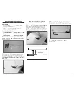
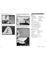
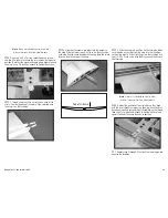
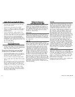
The recommended Center of Gravity (CG) location for your
model is 8
1
/
2
-inch to 9-inch (216mm–229mm) located at the
wing root near the fuselage. Measure back from the leading
edge as shown and mark the location of the CG on the top of
the wing with a felt-tipped pen.
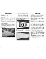
With a helper, lift the aircraft with your index finger at the
location marked on the wing. If the nose of your aircraft
hangs low, add weight to the rear of the aircraft. If the tail
hangs low, add weight to the nose of the aircraft. Stick-on
weights are available at your local hobby store and work well
for this purpose.
After the first flights, the CG position can be further adjusted
for your personal preference.
Note
: The receiver battery can be located in multiple
locations in your aircraft. Although the location
shown is for the installation of the recommended
engine, please locate the battery in the fuselage
to achieve the correct Center of Gravity without
adding additional weight to your aircraft.
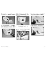
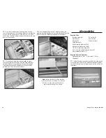
1. Secure a 24-inch (610mm) servo extension on the
batter pack lead. Wrap the battery in foam and secure its
location using a hook and loop strap.
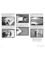
2. Once the receiver battery has been installed, use six
2mm x 8mm sheet metal screws and a #1 Phillips screwdriver
to secure the cover over the battery compartment.
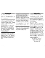
Control Throws
Setting the control throws for your model does require some
attention to detail. To correctly set the throws, it is highly
suggested to use the following procedure to achieve the
greatest mechanical advantage from your servos:
1. Determine the maximum amount of control surface
throw from the throws listed. Use the high-rate throws to
set the maximum amount of throw, then use your computer
radio for the lower rate listed.
2. Set the Travel Adjust to about 15% under the max.
(On a JR transmitter, that is 135%.) Make sure to set both
directions during this process.
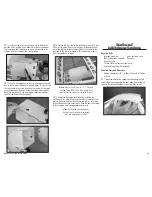
3. Adjust the position of the clevis on the control horn
and position of the ball link on the servo arm to achieve
the high rate throws listed. It is highly recommended not
to change the position on the servo arm unless absolutely
necessary. Use Travel Adjust (ATV) to finalize the throws
(that is why we left a little margin in the percentages).
4. If setting a dual elevator or aileron, match the linkage
locations. Increase or decrease the Travel Adjust (ATV) a
few points as necessary to fine-tune the throws to match
up left and right sides and up and down throws so all is
symmetrical.
This is all necessary to tune the mechanical advantage
as best as possible. When setting up your model, the
mechanical advantage will be less because of the large
throws, and thus, the servo will work harder and wear faster.
Using an insufficient servo for the job, or trying to get too
much throw, will cause something to give; probably the
servo.
There isn’t an exact geometry to the linkage, as it depends
on how much throw each individual modeler requires. The
linkage geometry should always be maximized so the servo
isn’t working any harder than it has to.


