
HandiQuilter.com
Page 39
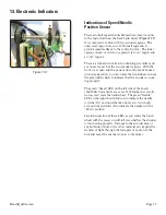
When you fi rst power on the HQ
Sweet Sixteen, each of
the LEDs in the Control Pod LED bank will briefl y fl ash
in succession. Following that initial fl ash, the left-most
LED (labeled HrtBt) should fl ash in a “heart beat” fashion
to indicate that the processor is running and is not locked
up. If the processor is locked up, these LEDs will be
locked in either an “On” or an “Off” state.
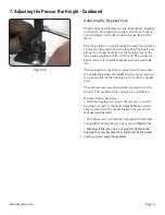
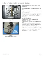
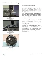
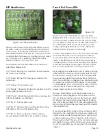
A description of each of the 8 LEDs and its function is
listed below (
Figure 13.4
).
• D3 “HrtBt”: Flashing in a “heartbeat” fashion indicates
the processor is running.
• D6 “Speed”: Flashes 100 times per revolution of the
hand wheel.
• D5 “Option”: Not currently used.
• D4 “Needle”: Should be Off when the needle is in the Up
position and On when it is down.
• D10 “Test 4”: Should fl ash rapidly when communication
with the handlebars is established.
• D9 “Test 3”: Not currently in use.
• D8 “Test 2”: Indicates the current Needle Stop setting
(Off indicates Down and On indicates Up).
• D7 “Test 1”: Turns on when the “Start” button is
pressed, indicating that the motor should be running.
Figure 13.4 LED Identifi cation
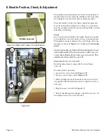
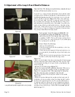
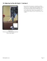
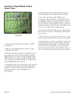
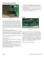
Figure 13.5
Near the top of the Control Pod are two green LEDs
(
Figure 13.5
). The control pod receives an input of +48V
from the two power supplies and it converts this voltage
into two different voltage levels. The left LED (closest to
the +18Vdc label) indicates that the 18V power is func-
tioning and the right LED (closest to the +5Vdc label)
indicates that the 5V power is functioning.
If either of these LEDs is not on, fi rst disconnect all cables
from the C-Pod other than two of the power cables at
the top (only plug in J14 and J15, not the black and red
cable). If the LED(s) are still not on, then there may be
an issue with one or more of the on-board power supplies.
If the LEDs both begin working again, this may indicate
that one of the peripherals is shorting out the C-Pod.
Begin plugging the cables back in one at a time (powering
off between the connection of each cable) until you fi nd
the cable that is causing the issue. If it is a display cable,
then the issue could be the internal cable or the display
itself. You could then try plugging that cable back in with
the display disconnected to verify whether it is the cable
or the handlebar. If it is one of the other cables, then the
problem may be related to that particular component
(needle/speed encoder or motor driver).
However, if both LEDs are off, check to make sure the
black power cord is plugged in and the power switch is
ON. A volt meter may be used to verify that there is 24V
DC between the red and yellow power lines (J14) and be-
tween the yellow and black (J15). Measuring between the
left-most pin of J14 and the right-most pin of J15 should
show about 48V DC.
If you do not have 24V at either of those connectors (48V
between the two combined), then the power supplies and
attached cables should be inspected for any short circuits
or wires breaking away from connectors, both on the C-
Pod side and on the P-Pod side. If the volt meter indicates
that the 48V is present at the C-Pod power connector and
the C-Pod power LEDs are off, then the C-Pod should be
replaced.
LED Identifi cation
Control Pod Power LEDs