background image

HandiQuilter.com

 Page 27

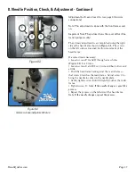
Figure 8.3

F

H

G

D

C

E

8. Needle Position, Check, & Adjustment - Continued

Adjustment for X axis: Cover On  (see page 14 for wire 

connections)

Note: This adjustment is done with the front frame cover 

on. 

Important Note: The picture shows the cover off for illus-

tration purposes only!

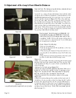
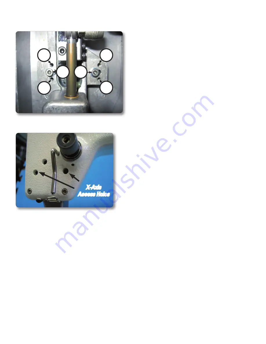
The primary adjustment is accomplished using the right 

side of the head frame shown in 

Figure 8.4

.  The screws 

on the left side are loosened to allow movement of the 

head frame.

If a correction is necessary:

• Loosen screws F, G and H through access holes 

(

Figure 8.4

) 2 or 3 turns.

• Loosen screws D and E 2 or 3 turns and back off screw C 

a little.

• Push the head frame back against the main frame so 

that screw C touches the main frame.  Adjust screw C to 

bring the needle to center in the needle plate.  

• Gently tighten screw E until it lightly touches the main 

frame

• Tighten screw D.  

Note: If the needle changes, repeat the 

process. 


• Repeat the process on the left side of the head frame.  

Note: If the needle changes, repeat the process.  

Figure 8.4

X-Axis access/adjustment holes

X-Axis 

Access Holes

Summary of Contents for HQ Sweet Sixteen

Page 1: ...SERVICE MANUAL 12 20 10 2010 Handi Quilter Inc Designed by a Quilter for Quilters...

Page 2: ...f the Loop Lift and Needle Distance Adjusting Needle Height Adjustment of the Stop Finger Adjusting the Needle Height with Cylinder Tool Electronic Adjustments and Indicators Indications of Speed Need...

Page 3: ...nal or more serious problems than the original issue Safety must be considered when working on any machine Safety warnings are included throughout this manual where appropriate but these warnings do n...

Page 4: ...ical Power LED Power Consumption Hopping Foot Stroke Lift Needle Bar Stroke Take Up Stroke Lubrication main components Lubrication of hook 210 mm X 406 mm 8 25 X 16 Min 75spm Max 1500spm 134 135 X 7 1...

Page 5: ...m Uses 2 0 mm Allen tool Tension assembly three hole thread guide motor pulley hook 3 5 mm Allen socket head cap screw class 8 8 5 6 Nm Uses 4 mm Allen tool Front cover large Belt tensioner Drive trai...

Page 6: ...ly All the above in box w booklet HQ Lubricant Order Numbers The HQ Sweet Sixteen lubricating schedule should be followed every year up to every two years to ensure top mechanical performance Machine...

Page 7: ...lubricate the hook less frequently After the lubrication of the hook it is recommended that one momentarily sew on scrap material before resuming the sewing of the quilt Failure to do so may result in...

Page 8: ...orifice articulating link take up lever and needle bar driver 3 places 4 Green IsoFlex NCA 15 Inside caged needle bearings 2 places 5 Orange GLY 151 Add grease sparingly to the presser bar slide and...

Page 9: ...ction is necessary Loosen the jam nut reposition and tighten the jam nut 10 mm open end wrench Check 2 Make sure that a gap of 1 0 mm to 1 5 mm ex ists between the frame and the hand wheel Note The ha...

Page 10: ...ion discs and cone spring See Figures 1 5 through 1 10 Clear and reassemble Note On very rare occasions if the ma chine has been used an extreme amount it is possible for a groove to be worn into the...

Page 11: ...ity Reinstall the top tension parts on the split bolt and then the assembly into the machine front cover and tighten the set screw Radial postion When the top tension assembly is prop erly installed i...

Page 12: ...od use a grounding mat and wrist strap Connect the two ground clips to the bare threads of the hopping foot Figure 2 4 Caution Make sure the machine is unplugged from the wall before removing the C po...

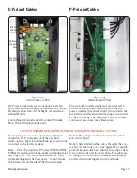
Page 13: ...nd yellow position labeled J15 on board F Right cable red and black position labeled both J16 and Motor on board A B C Figure 2 6 C Pod Circuit Board Identification Detail A Encoder connection B Motor...

Page 14: ...ove the 3 screws on the left side shown circled in orange in Figure 2 9 Slide the power sup ply to the left and unplug the bottom cable Figures 2 9 2 11 Important Note Insulator material must cover al...

Page 15: ...Page 15 Figure 2 13 Location of encoder disc and sensor circled Figure 2 12 Cable Identification F Motor driver board with motor power top B Motor driver center G Motor bottom F G B Internal Wiring R...

Page 16: ...portant note Two ground wires are fixed with a socket head cap screw and star washer shown circled in Figure 2 15 for safety grounding Important note Insulator material must cover all metal on the bac...

Page 17: ...see Figure 2 7 carefully push the excess cable back into the machine as there is no room in the pod for extra cable The cables are to the right of the drive train bracket and therefore protected from...

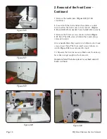
Page 18: ...mm handle Allen wrench 9 Remove the 5 frame screws shown circled in Figure 2 23 Note The fifth screw is behind the C pod and was removed in step 4 4 mm handle Allen May need 4 mm L Allen tool to brea...

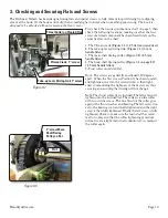
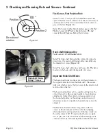
Page 19: ...dle Allen 5 Trust collar on slanted flat Note The screws are generally positioned 120 degrees apart When the first screw Position 1 has been located and tightened on a flat the second screw is then ti...

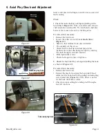
Page 20: ...emove axial play not the hook shaft pulley or the setting can be thrown off which may make it so needle to hook distance cannot be adjusted The HQ Sweet Sixteen utilizes long collars with two screws i...

Page 21: ...2 Adjust so that minimal to no play is detected Provisionally set the screws Check that the shaft has minimal play and no tightness from the collar being too tight by rotating the shaft through a few...

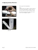
Page 22: ...ls required 5 mm handle Allen Check 1 The base plate must be adjusted so that the rubber feet will sit flat on a planed surface Note This is done on a precision surface plate at the factory during ass...

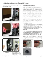
Page 23: ...mportant Do not over tighten the belt as this will make the machine too tight and difficult to turn and may cause other undesirable issues If a correction is necessary Insert a 4 mm handle Allen tool...

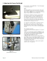
Page 24: ...t It is important to check this before resetting the presser bar height in case the end user has changed the foot height Improper setting of the presser bar height and foot height can cause stitch pro...

Page 25: ...ed hook life The hopping foot should be no more than 0 5 mm above the needle plate when the needle is in the lowest position It is permissible for the hopping foot to touch the needle plate The end us...

Page 26: ...such as the needle plate The needle must be centered in the stitch hole of the nee dle plate as shown in Figure 8 1 2 mm and 3 mm handle Allen Check with needle eye ush with the needle plate do not c...

Page 27: ...allow movement of the head frame If a correction is necessary Loosen screws F G and H through access holes Figure 8 4 2 or 3 turns Loosen screws D and E 2 or 3 turns and back off screw C a little Pus...

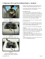
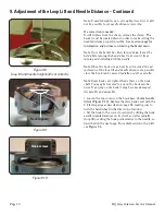
Page 28: ...e the following Remove the needle plate Turn the hand wheel until the needle bar is at its low est position or BDC Place the loop lift clamp with special protective com pression pad on the needle bar...

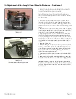
Page 29: ...that the basket needle guard be rotated down out of the way to allow correct adjustment of the needle distance setting See Figures 9 5 and 9 6 Rotate the basket out of the way to facilitate the needle...

Page 30: ...stments of the loop lift and needle distance are possible since the hook can be moved radially as well as axially Note Some hooks are tighter than others on the hook shaft You may be tempted to pry on...

Page 31: ...Allen tool while providing resistance against the adjust ment by holding the hook in place with your other hand Carefully rotate the hook on the hook shaft to set the loop lift Figure 9 8 Carefully s...

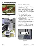
Page 32: ...t a screwdriver through the access hole Figure 10 2 Hold the needle bar with your other hand to provide resistance against the adjustment so the needle bar will not fall down out of the driver Loosen...

Page 33: ...ened Failure to observe this caution can result in the uncoupling of the nee dle bar from the needle bar driver If this happens do not run the machine Remove the front frame cover reassemble the needl...

Page 34: ...am the machine If an adjustment is necessary Loosen screw A Figure 11 1 and adjust the stop finger so the proper clearance is achieved as shown in Figure 11 2 Important Ensure that the stop finger sta...

Page 35: ...e as shown in the adjustment of loop lift and needle distance section Check loop lift If the machine requires a loop lift adjustment remove the stop finger and hook body from the machine Follow the st...

Page 36: ...the cylinder tool gently against the needle Figure 12 5 6 Reinstall the hook and set loop lift at 2 2 mm and reset needle distance See Adjustment of the Loop Lift and Needle Distance Section 5 Sight t...

Page 37: ...d see the green LEDs flash to indicate that the encoder is work ing properly The green Speed LED on the left side of the board should flash on and off at a rate of 100 flashes per revolu tion as you r...

Page 38: ...n the display a This can be caused by the Speed Needle sensor missing some of the speed pulses First run the Speed test within the Diagnostics menu on either the front or rear handlebar refer to the D...

Page 39: ...LEDs is not on first disconnect all cables from the C Pod other than two of the power cables at the top only plug in J14 and J15 not the black and red cable If the LED s are still not on then there m...

Page 40: ...and has not been damaged both front and rear If this is okay then the issue is related to the internal handlebar cable or possibly the C Pod The internal handlebar cable going to the front could be da...

Page 41: ...2010 Handi Quilter Inc All rights reserved Printed in the USA 12 20 10 Designed by a Quilter for Quilters Handi Quilter Inc 445 N 700 W North Salt Lake UT 84054 1 877 697 8458 www handiquilter com...

Reviews: