
Page 12
HQ Sweet Sixteen Service Manual
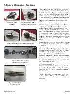
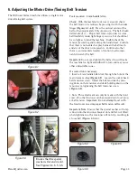
Figure 2.4
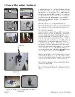
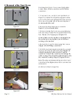
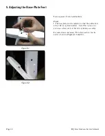
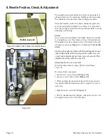
Figure 2.1
A
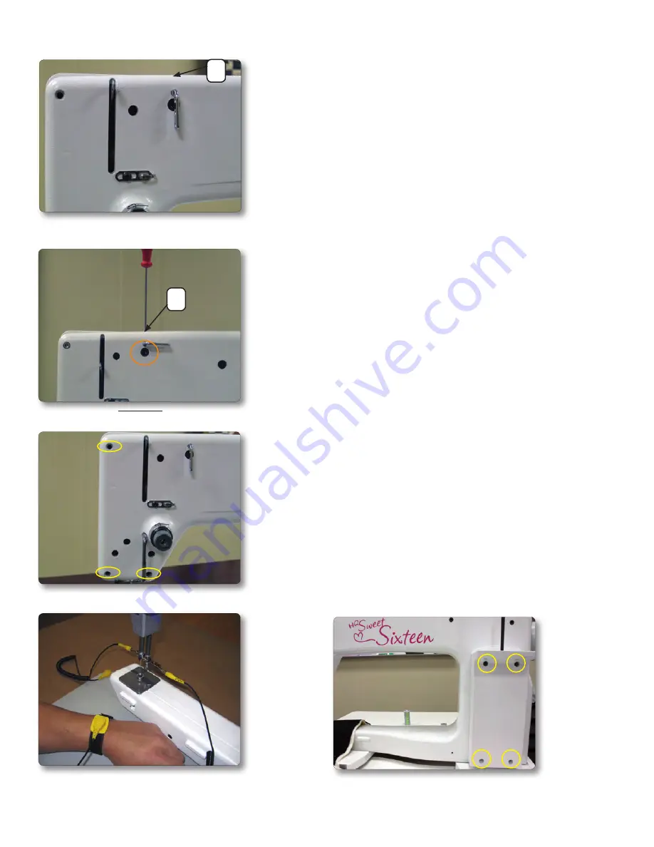
Figure 2.3
Figure 2.5
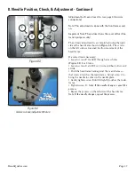
Figure 2.2
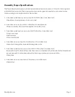
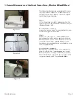
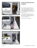
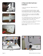
2. Removal of the Front Cover
Tools Required: 2 mm, 3 mm, 4 mm handle Allen,
4 mm L Allen, #3 fl at screwdriver and #2 Phillips
screwdriver.
1. Loosen set screw on top of cover (position A in
Figure 2.1). Rotate the 3-hole thread guide to allow
access to the frame screw (Figure 2.2), then re-snug
the screw so the guide will not become misplaced.
(
2 mm handle Allen tool
)
2. Remove the three frame screws circled in
Figure 2.3 (3 mm handle Allen)
3. Before removing the C-pod, use a grounding mat
and wrist strap. Connect the two ground clips to the
bare threads of the hopping foot.
(Figure 2.4)
Caution: Make sure the machine is unplugged from
the wall before removing the C-pod or whenever
working on the machine.
4. Remove the “C-pod” by unscrewing the 4 screws.
(Figure 2.5) (#2 Philips screwdriver)
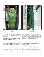
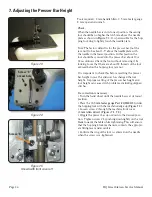
5. With the machine properly grounded to a ground-
ing mat, and with a ground wrist strap
(Figure 2.4),
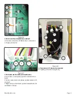
carefully unplug the cables from the C-pod. Be
careful not to touch the circuit board or damage the
cables or plugs. They should be pulled straight out by
the connector housing. (Page 13, Figures 2.6-2.8)
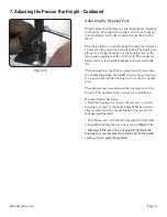
Note:
The plugs are labeled and keyed on the C-pod
circuit board. See
Figures 2.6- 2.13
for reconnection
information.
(Continue to Step 6 on page 14.)
A