background image

       All rights reserved. No part of this publication may be reproduced and/or published by means of print, 
photocopy, microfilm or in any other way or form, without prior written permission from the manufacturer. This 
also applies for the accompanying drawings and diagrams. The manufacturer  reserves the right to change 
parts at any time, without prior or direct notification to the customer. The contents of this manual may also be 
changed without prior warning. This manual is intended for the standard models of the lift. The manufacturer 
therefore cannot be held liable for any damage resulting from specifications that differ from those of the 
standard model of the lift supplied to you. 
This manual has been compiled with the best intentions and every possible care but the manufacturer cannot
accept responsibility for any errors in this manual or for the consequences thereof.

EN


       Tous droits réservés. Aucun élément de cette édition ne peut être copié et/ou publié par impression, 
photocopie, microfilm ou de quelque façon que ce soit sans l’autorisation écrite préalable de le fabricant. Il en va 
de même pour les plans et schémas correspondants. le fabricant se réserve le droit de modifier à tout moment 
des pièces sans avis préalable ou direct au client. Le contenu de ce manuel peut également être modifié sans 
préavis. Ce manuel est valable pour l’élévateur en version standard. le fabricant décline dès lors toute 
responsabilité pour les dommages éventuels dus au changement des spécifications par rapport à la version 
standard de l’élévateur qui vous a été fourni.
Ce manuel a été composé avec tout le soin possible mais  le fabricant ne peut être tenu pour responsable 
d’erreurs éventuelles dans ce manuel ni de leurs conséquences.

FR

Summary of Contents for FREECURVE MONORAIL

Page 1: ...Classic Elegance Alliance IN S E R T D IR E C T IO N T E S T S I D E FREECURVE I N S T A L L A T I O N M A N U A L MONORAIL MANUAL D INSTALLATION...

Page 2: ...e care but the manufacturer cannot accept responsibility for any errors in this manual or for the consequences thereof EN Tous droits r serv s Aucun l ment de cette dition ne peut tre copi et ou publi...

Page 3: ...nstallatie instructies voor de standaard uitvoeringen en de optionele uitbreidingen Wir freuen uns dass Sie sich f r einen Handicare Treppenlift entschieden haben In diesem Handbuch f r den Sitztypen...

Page 4: ...5 mm 1 1 1 5 mm 7 mm 8 mm 13 mm 3 mm 4 mm 7 mm 5 mm 8 mm INSTALLATION MANUAL 2 MANUEL D INSTALLATION...

Page 5: ...caleras solo debe ser realizada por un t cnico cualificado Las ltimas instrucciones del salvaescaleras y las instrucciones para las diversas opciones est n disponibles para ser descargadas en www hand...

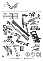
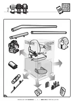
Page 6: ...FSR30021 1 2 1 INSTALLATION MANUAL 4 MANUEL D INSTALLATION...

Page 7: ...A B 0 mm A 7mm 4 mm 1 2 3 15m 2 OPTION INSTALL FOLDING HINGE INSTALLER RAIL ESCAMOTABLE 2 3 2 2 2 1 2 4 INSTALLATION MANUAL 5 MANUEL D INSTALLATION...

Page 8: ...x x 10Nm AA10622 7mm 4 2 External curves only TIP Courbes externes seulement 89 Lb In 2 7 2 6 2 5 2 8 INSTALLATION MANUAL 6 MANUEL D INSTALLATION...

Page 9: ...C0051310 2 Average La moyenne m a x 4 5 0 USA ONLY TATS UNIS UNIQUEMENT 2 12 2 11 2 9 2 10 10x24mm INSTALLATION MANUAL 7 MANUEL D INSTALLATION...

Page 10: ...SHORT 0 Nm 0 Nm 0m m 8 mm LONG 5 mm 2 15 2 13 2 14 2 16 2 A B INSTALLATION MANUAL 8 MANUEL D INSTALLATION...

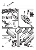
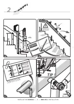
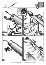
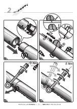
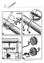
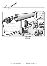
Page 11: ...2 19 2 20 2 18 2 17 2 INSTALLATION MANUAL 9 MANUEL D INSTALLATION...

Page 12: ...electrical equipment and wiring shall conform to the require ments of NEC and ANSI NFPA70 L installation de l quipement lectrique et le c blage doivent tre conformes aux exigences de la NEC et ANSI NF...

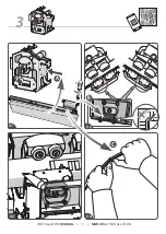
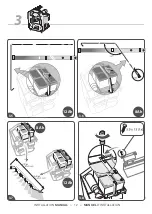
Page 13: ...B A C 3 3 4 3 3 3 2 3 1 INSTALLATION MANUAL 11 MANUEL D INSTALLATION...

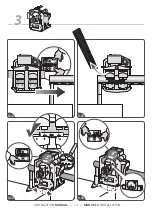
Page 14: ...3 12 Ah 8 Ah 12 Ah 8 Ah 3 8 3 7 3 6 3 5 INSTALLATION MANUAL 12 MANUEL D INSTALLATION...

Page 15: ...IN S E R T D IR E C T IO N T E S T S I D E 1 2 1 2 1 2 1 2 3 11 3 10 3 9 3 Green Vert INSTALLATION MANUAL 13 MANUEL D INSTALLATION...

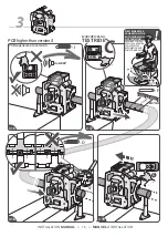
Page 16: ...3 15 3 14 3 13 3 12 3 10 INSTALLATION MANUAL 14 MANUEL D INSTALLATION...

Page 17: ...AFTER CALIBRATION THE AUTOSWIVEL WILL NOT FUNCTION PCB higher than version S TESTRIDE PCB sup rieure la version S MARCHE D ESSAI PREMI RE COURSE APR S LA CALIBRATION LE PIVOTEMENT AUTOMATIQUE NE FONC...

Page 18: ...Beep Beep Beep Beep Beep Beep Beep J 2 4 Ghz 915 MHz 3 21 3 22 3 20 3 FR 868MHz Beep Beep Beep max DANS LE CAS D UN B TIMENT PUBLIC 10 INSTALLATION MANUAL 16 MANUEL D INSTALLATION...

Page 19: ...CHILD 4 mm 3 26 3 23 3 24 3 25 3 FR 868MHz INSTALLATION MANUAL 17 MANUEL D INSTALLATION...

Page 20: ...3 B 4 4 4 2 4 1 4 4mm 6mm CHAIR SI GE AUTOSWIVEL PIVOTEMENTAUTOMATIQUE OPTION INSTALL POWERED FOOTREST INSTALLER REPOSE PIEDS AUTOMATIQUE ROUGE BLEU FOOTREST REPOSE PIEDS INSTALLATION MANUAL 18 MANUEL...

Page 21: ...com T 3172 576 8888 F 3172 574 3435 1 Ratedspeed 0 11m s 21 7 ft min Rackandpiniondrive Dateofmanufacture ASME 18 1 to be used for inspections and tests lbs A C 11P00346 B 4 8 4 6 4 7 4 5 4 OPTION FRA...

Page 22: ...STOP CLICK OPTIONAL 3mm A B C 4 9 4 10 4 INSTALLATION MANUAL 20 MANUEL D INSTALLATION...

Page 23: ...2 5 mm 4 4 11 4 12 4 13 4 14 4 15 4 16 INSTALLATION MANUAL 21 MANUEL D INSTALLATION...

Page 24: ...5 1 1 15 100 mm 400 mm 10 mm 5 INSTALLATION MANUAL 22 MANUEL D INSTALLATION...

Page 25: ...22H00011 K 5 3 5 2 5 5 5 4 5 6 3 x 50 3x INSTALLATION MANUAL 23 MANUEL D INSTALLATION...

Page 26: ...6 6 4 6 3 6 2 6 1 INSTALLATION MANUAL 24 MANUEL D INSTALLATION...

Page 27: ...6 Seulement pour les essais 6 8 6 7 6 6 6 5 INSTALLATION MANUAL 25 MANUEL D INSTALLATION...

Page 28: ...INSTALLATIEHANDLEIDING DEINSTALLATIONANLEITUNG MANUALE PER DISINSTALLAZIONE MANUAL DE DESINSTALACI N MANUAL DE DESINSTALA O AVINSTALLASJONSMANUALEN AVINSTALLATIONSMANUAL AFINSTALLATIONSMANUAL R UTILI...

Page 29: ...X 1 17 3 mm 6 mm 3 mm 8 8 1 8 5 8 3 8 6 8 4 8 2 INSTALLATION MANUAL 27 MANUEL D INSTALLATION...

Page 30: ...X 1 15 8 8 mm 8 mm 8 mm DU HAUT 8 11 8 7 8 8 8 9 8 10 8 12 INSTALLATION MANUAL 28 MANUEL D INSTALLATION...

Page 31: ...A B 7 mm 8 8 15 8 16 8 14 8 13 INSTALLATION MANUAL 29 MANUEL D INSTALLATION...

Page 32: ...ATTACHMENTS ANNEXE ANEXO ANHANG ANNEXE APPENDICE BILAG BIJLAGE ZALACNIK ANEXO BILAGO TILBEH R INSTALLATION MANUAL 30 MANUEL D INSTALLATION...

Page 33: ...0 mm A HINGE 5 mm RAIL ESCAMOTABLE B A C D E A 1 A 2 A 4 A 3 INSTALLATION MANUAL 31 MANUEL D INSTALLATION...

Page 34: ...A B 5Nm M6 900 4mm 4mm 44 Lb In A A 6 A 5 A 8 A 7 INSTALLATION MANUAL 32 MANUEL D INSTALLATION...

Page 35: ...the back of the frame 5 F hren Sie das Kabel weit genug durch die Achse A Dr cken Sie mit einer Zange den speziellen Kabelschuh auf das Kabel B 6 L sen Sie den Stecker vom Plus Kontakt 7 Positionieren...

Page 36: ...footrest and lights for correct operation 11 Schrauben Sie den Sitz an der Fahrein heit fest A Schlie en Sie die Stecker des Sitzes wieder an B 12 Verbinden Sie das lose Kabel mit dem Kabel der Platin...

Page 37: ...vloer en de eerste steun op de verdieping 1 Positionieren Sie die Schiene auf der Treppe Der Abstand zur Wand ist auf der beiliegende Zeichnung er w hnt 2 Nach die Installation des Gelenks nach die An...

Page 38: ...steunen C 5 Fahren Sie die Fahreinheit auf der Schiene und platzieren die Fahreinheit danach in der Kurve der Schiene 6 berpr fen Sie mit einer Wasserwaage ob die Fahreinheit ge nau senkrecht ist 7 W...

Page 39: ...THE NORMAL PROCEDURE FOR CALIBRATING THE LIFT 2x BEEP 2 sec CORRECTION DE POINT DE CHARGE _ STANDARD PCB sup rieure la version S Premi re course SE R F RER AU MANUEL POUR SUIVRE LA PROC DURE NORMALE P...

Page 40: ...LIBRATING THE LIFT 2x BEEP 2 sec PCB higher than version S CORRECTION DE POINT DE CHARGE _ POINT D ARR T LE PLUS BAS PCB sup rieure la version S Premi re course SE R F RER AU MANUEL POUR SUIVRE LA PRO...

Page 41: ...FOLLOWTHE NORMAL PROCEDURE FOR CALIBRATING THE LIFT 2x BEEP 2 sec AJOUT DE POSITION DE CHARGE PCB sup rieure la version S Premi re course SE R F RER AU MANUEL POUR SUIVRE LA PROC DURE NORMALE POUR LA...

Page 42: ...HE NORMAL PROCEDURE FOR CALIBRATING THE LIFT 2x BEEP 2 sec SUPPRESSION DE POSITION DE CHARGE PCB sup rieure la version S Premi re course SE R F RER AU MANUEL POUR SUIVRE LA PROC DURE NORMALE POUR LA C...

Page 43: ...OWTHE NORMAL PROCEDURE FOR CALIBRATING THE LIFT 2x BEEP 2 sec CORRECTION DE POINT DE RAIL ESCAMOTABLE PCB sup rieure la version S Premi re course SE R F RER AU MANUEL POUR SUIVRE LA PROC DURE NORMALE...

Page 44: ...BEEP DEALER DEALER PCB higher than version S 6x BEEP 6x BEEP CHAIR CALIBRATION CALIBRATION DE SI GE REVENDEUR REVENDEUR PCB sup rieure la version S C A B C A B I 1 I 2 INSTALLATION MANUAL 42 MANUEL D...

Page 45: ...INKING 3 sec 3 sec REMOTE CONTROL RF BLINKING GREEN BLINKING GREEN T L COMMANDE RF TATS UNIS UNIQUEMENT VERT CLIGNOTANT VERT CLIGNOTANT SOLID GREEN VERT SOLIDE BLINKING GREEN VERT CLIGNOTANT B A J 5 J...

Page 46: ...J 2 J 6 ON PAGE 43 1 2 50 m CHANGING CHANNELS 4 POSSIBLE POSITIONS 4 POSITIONS POSSIBLES TATS UNIS UNIQUEMENT CHANGEMENT DES CANAUX J 2 4 GHz RF 915 MHz A B C A A B B J 8 J 9 J 10 J 11 J 12 INSTALLATI...

Page 47: ...GREEN RF 2 4Ghz BLUE RF 915Mhz RECHARGEABLE J 16 J 15 J 14 J 13 TATS UNIS UNIQUEMENT TATS UNIS UNIQUEMENT J 2 4 GHz RF 915 MHz 2x 2x 2x B A 2x 2x INSTALLATION MANUAL 45 MANUEL D INSTALLATION...

Page 48: ...1 17 K 3 K 2 K 1 K 4 K WALL SUPPORT SUPPORT MURAL B INSTALLATION MANUAL 46 MANUEL D INSTALLATION...

Page 49: ...D K9 K6 E5 FOOTREST CHAIR SWIVEL 4mm C B 3x 2x STOP A Pz 1 A B L 3 L 2 L 1 L 4 L EMERGENCY OPERATION FONCTIONNEMENT D URGENCE INSTALLATION MANUAL 47 MANUEL D INSTALLATION...

Page 50: ...4x REINSTALL LIFT SEE MANUAL R INSTALLEZ MONTE ESCALIER VOIR LE MANUEL STOP L 8 L 7 L 6 L 5 L INSTALLATION MANUAL 48 MANUEL D INSTALLATION...

Page 51: ......

Page 52: ...Deutschland Tel 49 0 571 973398 55 Fax 49 0 571 973398 56 data handicare com Prism Medical Inc 10888 Metro Court St Louis MO 63043 United States of America Toll Free 1 866 891 6502 Local 314 692 9135...

Reviews: