20
COMPRESSOR INSTALLATION & START-UP GUIDE
REVISION M
8. Compressor Piping
8.1.
To avoid abnormal vibration and noise
pay close attention to how the
compressor is piped.
8.2.
The welding for the compressor should
contain at least 15% Argentina as an
ingredient. Once all piping is completed,
perform a pressure test to ensure there
are no leaks (maximum compressor
pressure 350 psi or 24 bar). The
cleanliness
of the system after pipe
welding should help avoid any swarf or
debris operating inside the system that
can cause compressor damage during
operation.
8.3.
To avoid compressor harmonic vibration
transferred by the structure and piping to
the chiller while in operation, a cushion or
shock absorber should be installed on the
suction and discharge tube.
8.4.
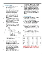
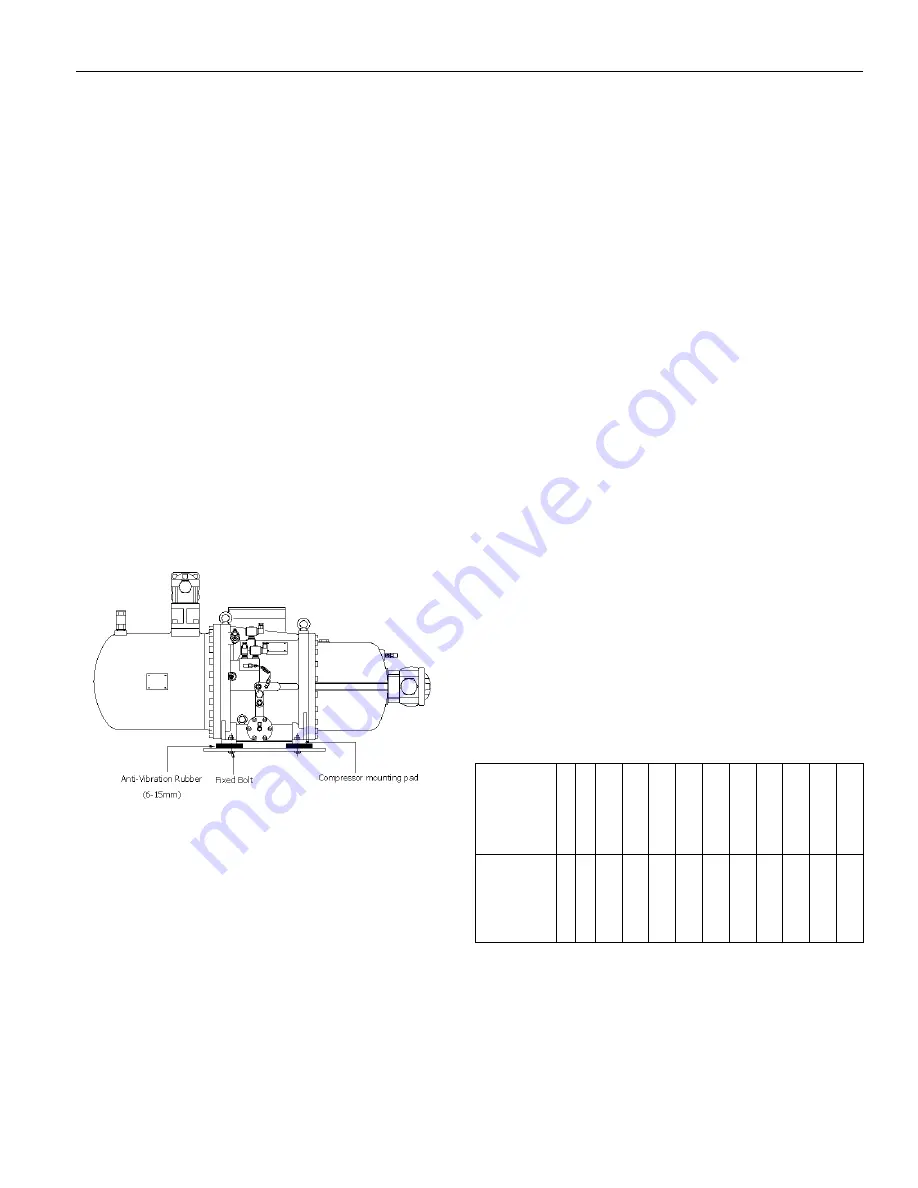
Refer to Figure 6-A showing a 6mm to
15mm.
Shock absorber installed under the
compressor-mounting pad to isolate the
vibration and noise transferred to other
portions.
Figure 8-A Absorber Installation
8.5.
In order to reduce vibration, copper tubes
for suction and discharge pipes are
recommended; copper suction and
discharge pipes will minimize the vibration
from the piping while the compressor is
running. In the case of steel piping, it is
very important for suitable welding to
avoid the inner stress on piping due to
harmonic vibration and noise, which will
reduce the compressor life.
8.6.
Remove oxidized impurities, swarf or
debris caused by welding on piping tubes,
if these impurities, swarf or debris are in
the compressor, the oil filter will be clogged
resulting in the lubrication system bearings and
capacity control system malfunctioning.
8.7.
The suction and discharge flanges are forged
steel that can be welded directly with piping
connectors (standard size for copper piping, if
connecting to steel piping contact your Hanbell
representative) After welding the flanges and
pipes, they should be cooled down by ambient
air;
water quenching is prohibited
. Do not use
water to cool down the pipes and flanges after
welding.
9. Electrical Wiring
9.1. If the compressor application is low voltage, the
following items should be considered:
9.2. Use conduit to insulate and protect the main
power cables between the control panel and
compressors’ electrical terminal box.
9.3. Press each main power cable connecting head
with bolts firmly on each power terminal in
electrical terminal box. Keep enough space
and distance between the main power cable
heads.
9.4. Choose suitable electrical accessories to meet
the required critical running conditions. An
AC-
3 contactor
is recommended to meet the rated
capacity of power. Select an overload protector
with a response time of
15 seconds
for
overload.
9.5. Ensure the electricity voltage drop between
each two phases is less than 2%. If unable to
reduce the length of main power cable then a
larger diameter of main power cable should be
chosen. Please refer to Figure 7-A shown
below.
9.6.
Main
power
cable
section
area
(mm
2
)
8
1
4
2
2
3
0
3
8
5
0
6
0
8
0
1
0
0
1
2
5
1
5
0
2
0
0
Maximu
m
continu
ous
current
(Amp)
5
5
8
0
1
0
0
1
2
5
1
4
5
1
7
5
2
0
0
2
3
0
2
7
0
3
1
0
3
6
0
4
2
5
Table 9-A Main Power Cable Size vs MCC
Maximum main power cable temperature is at
60°C. Maximum ambient temperature is at 35°C.


