


HAMWORTHY HEATING LTD
Page
PUREWELL Vari
Heat c
500001169/T
4
iv
Figure 11.8
Heat Exchanger Assembly PV70c/PV95c/PV110c ................................................................
47
Figure 11.9
Heat Exchanger Assembly PV140c/PV180c ..........................................................................
48
FIGURES
PAGE
Figure A1
Gas Data ................................................................................................................................
46
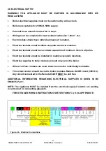
Figure B1.1
Electrical Supply .....................................................................................................................
47
Figure B1.2
External Control Wiring for Multiple Boiler Installation ...........................................................
48
Figure B2.0
In-line Fuse .............................................................................................................................
49
Figure C1
Flue Data ................................................................................................................................
50
Figure C1.1
Flue Resistance ......................................................................................................................
52
Figure C1.2
Open Flue (Natural Draught) B23 Flue System .....................................................................
52
Figure D1
Mechanical Ventilation Flow Rates ........................................................................................
53
Figure E1
Water Data .............................................................................................................................
54
Figure E1.1
Cold Feed and Vent Pipe Sizes .............................................................................................
54
Figure E1.2
Typical Piping Layouts ...........................................................................................................
55
Figure E1.3.1
Schematic for Single Boiler System .......................................................................................
57
Figure E1.3.2
Schematic for Single Boiler, Primary Circuit System .............................................................
57
Figure E1.3.3
Schematic for Single Boiler (External 0~10V) Multi Circuit System .......................................
58
Figure E1.3.4
Schematic for Multiple Boiler (Cascade) Primary Circuit System ..........................................
58
Summary of Contents for Purewell VariHeat 70c
Page 2: ......
Page 43: ...HAMWORTHY HEATING LTD 37 PUREWELL VariHeat c 500001169 T Figure 8 3 11 Operating phases ...
Page 44: ...HAMWORTHY HEATING LTD 38 PUREWELL VariHeat c 500001169 T Figure 9 0 Boiler Wiring Schematic ...
Page 65: ...HAMWORTHY HEATING LTD 59 PUREWELL VariHeat c 500001169 T Figure E1 2 Typical Piping Layouts ...
Page 70: ...HAMWORTHY HEATING LTD 64 PUREWELL VariHeat c 500001169 T NOTES ...
Page 71: ......


