


HAMWORTHY HEATING LTD
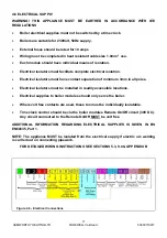
18
PUREWELL
Vari
Heat c
500001169/T
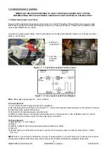
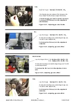
7.4 Combustion Checks
The boiler is factory preset, however, where checks need be undertaken during servicing to confirm correct
performance within the installation.
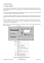
1) Put boiler into service mode (
Section 8.2.8.1
Page 29) to enable the High & Low CO
2
figures to be measured.
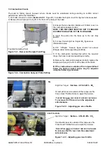
2) Remove the sample point plug from the front of the base of the boiler.
3) Ensure that an insertion distance of 100mm is set on
the combustion analyser probe.
NOTE: THIS DISTANCE MUST BE SET TO ENSURE
ACCURATE ANALYSIS OF THE FLUE GASES.
4) Insert the probe into the base up to the set stop
position .
5) For Low Fire & High Fire Target CO
2
figures see
information below.
6) CO = 0-50ppm: however figure should not exceed
200ppm under normal operating conditions.
7) If the combustion readings fall within the required
range, the boiler is set and operating correctly.
8) Remove the combustion analyser probe & replace the
sample point plug in the front of the base of the boiler.
9) If the combustion is outside of the ranges defined
below, the factory sealed valves may be adjusted
using the following procedure :
Flue Gas Sampling Point
Figure 7.4.1 - Removal of Sample Point Plug
Figure 7.4.2 - Combustion Analyser Probe Setting
High Fire Target
Nat Gas - 9.5% ±0.25% CO
2
If combustion level is outside of this range use the
Cross Head Throttle Screw to adjust the mixture.
T
HIS
SETTING
MUST
BE
CORRECT
BEFORE
CONTINUING
To increase the CO
2
level, turn the adjustment
anti-clockwise.
Figure 7.4.3.1 - Adjusting gas valve throttle
70c
High Fire Target
Nat Gas - 9.5% ±0.25% CO
2
If combustion level is outside of this range use the
Cross Head Throttle Screw to adjust the mixture.
T
HIS
SETTING
MUST
BE
CORRECT
BEFORE
CONTINUING
To increase the CO
2
level, turn the adjustment
anti-clockwise.
Figure 7.4.3.1 - Adjusting gas valve throttle
95c/110c/140c
Summary of Contents for Purewell VariHeat 70c
Page 2: ......
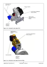
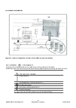
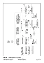
Page 43: ...HAMWORTHY HEATING LTD 37 PUREWELL VariHeat c 500001169 T Figure 8 3 11 Operating phases ...
Page 44: ...HAMWORTHY HEATING LTD 38 PUREWELL VariHeat c 500001169 T Figure 9 0 Boiler Wiring Schematic ...
Page 65: ...HAMWORTHY HEATING LTD 59 PUREWELL VariHeat c 500001169 T Figure E1 2 Typical Piping Layouts ...
Page 70: ...HAMWORTHY HEATING LTD 64 PUREWELL VariHeat c 500001169 T NOTES ...
Page 71: ......


