


HAMWORTHY HEATING LTD
14
PUREWELL
Vari
Heat c
500001169/T
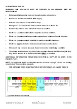
7.0 CHECKS PRIOR TO LIGHTING
IMPORTANT: BEFORE PROCEEDING TO LIGHT THE BOILER, ENSURE THAT THE PRE-
COMMISSIONING CHECKS HAVE BEEN CARRIED OUT AND THE RESULTS SATISFACTORY.
7.1 Boiler Gas System Leak Check
Ensure that the appliance manual gas service valve is in the OFF position. Although the boiler receives a gas
leak check and gas train component integrity check prior to leaving the factory, transport and installation may
have caused disturbance to unions.
A procedure guide is given below. Care must be taken not to allow leak detection fluid on or near any electrical
parts or connections.
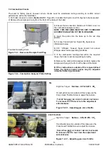
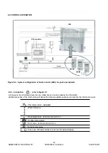
Figure 7.1.2 - Gas System Leak Check Diagram
Note: -
Main gas supply pressure - G20 - 20mbar
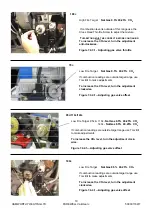
To Check Valve B
1) Turn off the electrical power and gas to the appliance.
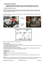
2) By unscrewing screw at Position X of Figure 7.1.1 remove the red gas pressure switch (L.H.S picture) or loosen
the test point valve plug (R.H.S picture).
3) Connect the manometer to gas valve test point.
4) With A, B closed open C and monitor manometer over a 2 minute period, a rise indicates a leak on valve B.
5) Reinstall red gas pressure switch or shut valve plug in test point.
To Check Valve A
1) Repeat steps 1, 2, 3 & 5 above.
2) Open C.
3) Open B to produce the main gas supply pressure between A and B.
4) Close B
5) System may be considered sound if over a period of 2 minutes any drop in pressure is less than 0.5 mbar
(0.2" wg.).
NOTE:
Allow a manometer stabilisation period of approximately 1-minute before each 2 minute check period.
Following soundness tests close valve B and remove manometer connections and tighten test points.
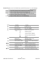
Figure 7.1.1 - Test Point Locations On Gas Valves
Position X
(Test Point)
Low Gas
Pressure
Switch
Summary of Contents for Purewell VariHeat 70c
Page 2: ......
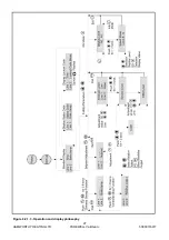
Page 43: ...HAMWORTHY HEATING LTD 37 PUREWELL VariHeat c 500001169 T Figure 8 3 11 Operating phases ...
Page 44: ...HAMWORTHY HEATING LTD 38 PUREWELL VariHeat c 500001169 T Figure 9 0 Boiler Wiring Schematic ...
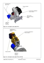
Page 65: ...HAMWORTHY HEATING LTD 59 PUREWELL VariHeat c 500001169 T Figure E1 2 Typical Piping Layouts ...
Page 70: ...HAMWORTHY HEATING LTD 64 PUREWELL VariHeat c 500001169 T NOTES ...
Page 71: ......


