HAMWORTHY HEATING LTD
84
Merley Boiler Sequence Controller
500001210/D
7 Plant diagrams
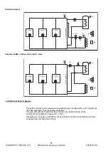
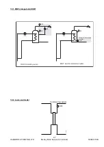
The various applications are shown in the form of basic diagrams and extra functions.
The basic diagrams show possible applications that can be implemented without the use
of multifunctional outputs.
7.1 Basic diagrams
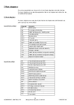
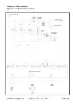
The basic diagrams are examples of plant that can be implemented with standard out-
puts requiring only a few settings.
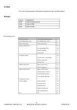
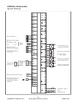
Diagram
Function
Q1
Boiler pump
Q2
1st heating circuit pump
Q3
DHW charging pump / diverting valve
Q4
circulating pump
Q14
System pump
Q15
H1 pump
Q25
Cascade pump
Q33
DHW intermediate circuit pump
Y1
1st Heating circuit mixing valve
Y4
Heat source shutoff valve
Y7
Maintained boiler return temperature
Y19
Primary controller
Y31
DHW primary controller mixing valve opening
Y32
DHW primary controller mixing valve closing
K6
Electric immersion heater
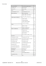
Legend mains voltage
Legend low
-
voltage
B1
Flow temperature sensor HK1
B12
Flow temperature sensor HK2
B2
Boiler temperature sensor TK1
B3
DHW sensor top
B31
2nd DHW sensor bottom
B35
DHW flow temperature sensor
B36
DHW charging sensor
B38
DHW temperature outlet sensor
B15
Flow sensor primary controller
B39
DHW circulation sensor B39
B7
Return sensor
B70
Cascade return sensor
B73
Primary circuit return sensor
B9
Outside sensor.
B10
Common flow sensor
RG1
Room unit 1
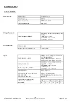
FS
Flow switch

