HAMWORTHY HEATING LTD
65
FLEET W series
500001211/F
APPENDIX E - WATER DATA
E1.1 Water Circulation System
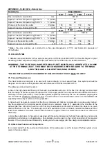
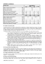
The Fleet boiler has a low water content and the requirements of minimum water flow are given in the above
table. To ensure these minimum requirements are achieved each boiler is fitted with an integral pump for
circulation through the boiler and primary circuit supplemented by an integral flow switch. Recommendations for
the water circulation system are given in BS 6644 and CP 342.
The following details are of particular importance for the correct installation of the water circulation system:
1) In a combined central heating and hot water system the hot water storage vessel must be of the
indirect cylinder or calorifier type. The hot water storage vessel should be insulated, preferably with
not less than 75mm (3”) thick mineral fibre, or its thermal equivalent.
2) Circulating pipe work not forming part of the useful heating surface should be insulated to help
prevent heat loss and possible freezing, particularly where pipes are run through roof spaces and
ventilated cavities. Cisterns situated in areas which may be exposed to freezing conditions should
also be insulated. Furthermore, insulation exposed to the weather should be rendered waterproof.
3) Drain valves must be located in accessible positions which permit the draining of the whole system,
including the boiler and hot water storage vessel.
4) Each boiler module has flow and return connections as detailed in the table above. Multiple boilers
should be connected by flow and return headers. Hamworthy strongly recommend that boilers are
connected in a primary circuit configuration utilising a low loss header arrangement to enable
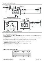
secondary circuits to be connected to the header. Figure E1.1.1 on the following page show typical
layouts.
5) Ideally, individual valves should be fitted to each module to enable isolation from the system,
however, the arrangement must comply with the requirements of BS 6644.
E1.2 Pressure Relief Valve (Safety Valve)
The most important single safety device fitted to a boiler is its safety valve. Each boiler module is provided with an
integral safety valve terminating in a 22mm stub pipe on the base of the boiler. BS 6644 provides comprehensive
information for the selection and location of safety valves and attention is drawn to the higher capacity
requirements of safety valves for pressurised hot water systems.
E1.3 Altitude Gauge (Water Pressure Gauge)
Every boiler or group of boilers should be provided with an altitude gauge complete with isolating valve. See
Figure E1.1.1 for typical position.
E1.4 Open Vent and Cold Feed Pipe.
Every boiler or group of boilers should have an open vent pipe and cold feed pipe installed between the boiler and
the first water isolating valve. The minimum bore (mm) of these pipes per installation is shown in the table. The
WATER DATA
BOILER MODEL
F40W
F50W
F60W
F70W
Water connections (Flow & Return) - BSP
R 1”
Maximum Water Pressure
-
bar g
6.0
Minimum Water Pressure
- bar g
Water content (not including headers) - litres
4.0
4.0
5.0
5.0
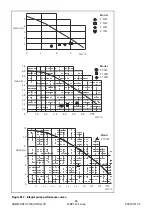
Design Flow Rate @ 20°C
∆
T Rise
-
litre/s
0.48
0.6
0.72
0.84
Waterside Pressure Loss @ 20°C
∆
T Rise
-
mbar
70 80 80 100
0.5
Residual pump performance available - mbar
270 200 140 60
F85W
F100W
F125W
F150W
Water connections (Flow & Return) - BSP
R 1”
Rp 1¼”
Maximum Water Pressure
-
bar g
6.0
Minimum Water Pressure
- bar g
Water content (not including headers) - litres
6.0
6.0
7.0
8.0
Design Flow Rate @ 20°C
∆
T Rise
-
litre/s
1.02
1.19
1.49
1.79
Waterside Pressure Loss @ 20°C
∆
T Rise
-
mbar
100 110 140 400
0.5
Residual pump performance available - mbar
420 340 220 300
Summary of Contents for F100W
Page 2: ......
Page 46: ...HAMWORTHY HEATING LTD 40 FLEET W series 500001211 F Figure 8 3 11 Operating phases...
Page 80: ......
Page 81: ......


