HAMWORTHY HEATING LTD
53
FLEET W series
500001211/F
APPENDIX C - FLUE DATA - Natural Gas
C1.0 FLUE SYSTEM
1. Detailed recommendations for flue systems are given in BS 6644, and IGE/UP/10. All flue discharges for plant
exceeding 150kW output must comply with the third edition of the 1956 Clean Air Act Memorandum.
WARNING: THE FLUE DISCHARGE FROM A FLEET BOILER WILL GENERATE A PLUME
AT THE TERMINAL EXIT. THIS MUST BE CONSIDERED WITH REGARD TO TERMINAL
LOCATION AND ADJACENT BUILDING FABRIC.
*FOR B23 INSTALLATIONS THE HAMWORTHY BOILER CONNECTION KIT ‘MUST’ BE USED*
C1.1 General Requirements
The Fleet
boilers are designed to be used with natural draught or room sealed flues. Flue systems should be
designed in accordance with regulations and with reference to BS 6644 and IGE/UP/10.
The following points should be noted:
a. Due to the high thermal efficiency of the boiler, condensation will occur in the flue. It is strongly recommended
that the design of the flue system recognises this. HHL supply plastic flue components and suitable terminals to
discharge the flue gases safely. The Fleet flue systems supplied by Hamworthy are non UV stabilised polypropylene
and are therefore suitable for internal use only. For external flue runs and termination, either use the dedicated kits
supplied by Hamworthy or refer to a chimney specialist .
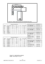
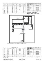
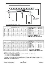
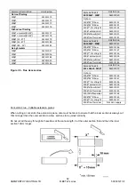
b. Care should be taken to ensure that the flue is installed such that any condensation is continuously drained.
Any flue system with a horizontal section should have a maximum slope of 3° upwards in the direction of the
exhaust gas flow. All joints should be such that any condensation is directed back down the slope to an open
drain connection in the flue. The drain pipe must be manufactured from a corrosion resistant material and be at
least 15mm diameter. It must also have a fall of at least 3° (approx. 50mm per meter) and connect to a drain via a
waste trap.
c. Boiler flue outlet sizes - A flue system designed with the same diameter as the boiler flue outlet may not provide
satisfactory performance in all applications. Consideration must be given to the correct calculation of the required
flue size. If in any doubt consult Hamworthy Heating Ltd who can supply a full flue design and installation service.
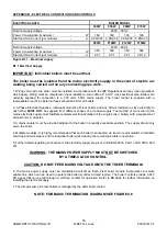
C1.2 Waste Gas Volume and Temperature.
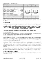
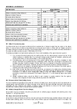
It is recommended that the volume and temperature of the waste gases used for design of the flue system are as
given in the above tables.
*
Note:-
Flue gas volumes are corrected to a flue gas temperature of 15°C and barometric pressure of
1013.25mbar.
FLUE DATA
BOILER MODEL
F40W
F50W
F60W
F70W
Flue connections (concentric) - mm
80/125
Approx. Flue Gas Temperature @ 80/60°C - °C (Gross)
60
Approx. Flue Gas Temperature @ 50/30°C - °C (Gross)
40
Pressure at the boiler flue outlet - Pa/mbar
150 150 150 150
Approx. Flue Gas Volume @ 9% CO
2
- m
3
/h*
52 65 78 91
F85W
F100W
F125W
F150W
Flue connections (concentric) - mm
80/125
100/150
Approx. Flue Gas Temperature @ 80/60°C - °C (Gross)
60
Approx. Flue Gas Temperature @ 50/30°C - °C (Gross)
40
Pressure at the boiler flue outlet - Pa/mbar
150 150 150 150
Approx. Flue Gas Volume @ 9% CO
2
- m
3
/h*
110 130 163 195
Summary of Contents for F100W
Page 2: ......
Page 46: ...HAMWORTHY HEATING LTD 40 FLEET W series 500001211 F Figure 8 3 11 Operating phases...
Page 80: ......
Page 81: ......

