HAMWORTHY HEATING LTD
6
FLEET W series
500001211/F
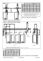
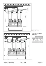
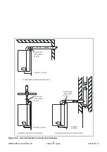
Figure 3.1.4 - Dimensions for cascade installation
Figure 3.1.5 - Dimensions for cascade installation
Figure 3.1.3 - Dimensions - individual flues
600
134
Boiler Model
A
470
80
350
350
350
450
450
470
80
470
80
570
100
570
100
D
B
380
80/125
80/125
80/125
100/150
100/150
380
380
480
480
C *
C * - for longer flues, the 80/125 connection can be adapted
to 100/150Ø or split into a twin duct system.
C ** - kits are available to adapt the flue ducts to 100, 130 or
150mm Ø depending upon the length of flue.
C **
F40/50W
Dim.
F60/70W F85/100W
F125W
F150W
Boiler Model
A
182
182
182
252
252
B
B
2 boilers or less - 150Ø
more than 2 boilers - 200Ø
200Ø
200Ø
F40/50W
Dim.
F60/70W F85/100W F125W
F150W
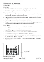
Figure 3.1.2 - Clearances individual vertical flues
560 crs
A
3°
B
Flue
Header Dia.
60
0
mi
n
406
300
550 max
Side View
Front View
Note: - maximum of four boilers in cascade.
Boilers can be individually flued or use the cascade flue kit as illustrated
Summary of Contents for F100W
Page 2: ......
Page 46: ...HAMWORTHY HEATING LTD 40 FLEET W series 500001211 F Figure 8 3 11 Operating phases...
Page 80: ......
Page 81: ......

