


Diagram: DR-
SG140
page 2 / 4
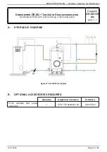
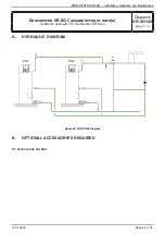
C. OPERATING DESCRIPTION
Despite the Dorchester DR-SGs being mounted in a hydraulic cascade, there is no communication
between the 2 products.
/!\ It is imperative that both the Dorchester DR-SGs have the same settings and the same operating
mode. If you use timer programming, you must ensure that the timestamping is correctly set on
both products.
Check that the loop flow rate and temperatures comply with the regulations; if necessary, adjust
the loop circulator adjustment valve and/or the mixing tap setpoint.
It should be remembered that the power of the Dorchester DR-SGs must be determined on the
basis of DHW consumption but also taking into account the heat losses of the distribution loop.
The balancing valves installed on the tank inlet tappings (cold water and loop return) can be used
to check that the flow rate ratios are equal to the power ratio.
A drain valve that is installed upstream of the mixing valve helps to balance the cold water, by
allowing hot water to be drawn off in the boiler room rather than flowing into the apartments.
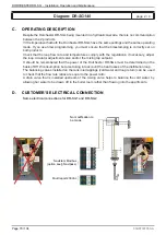
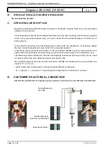
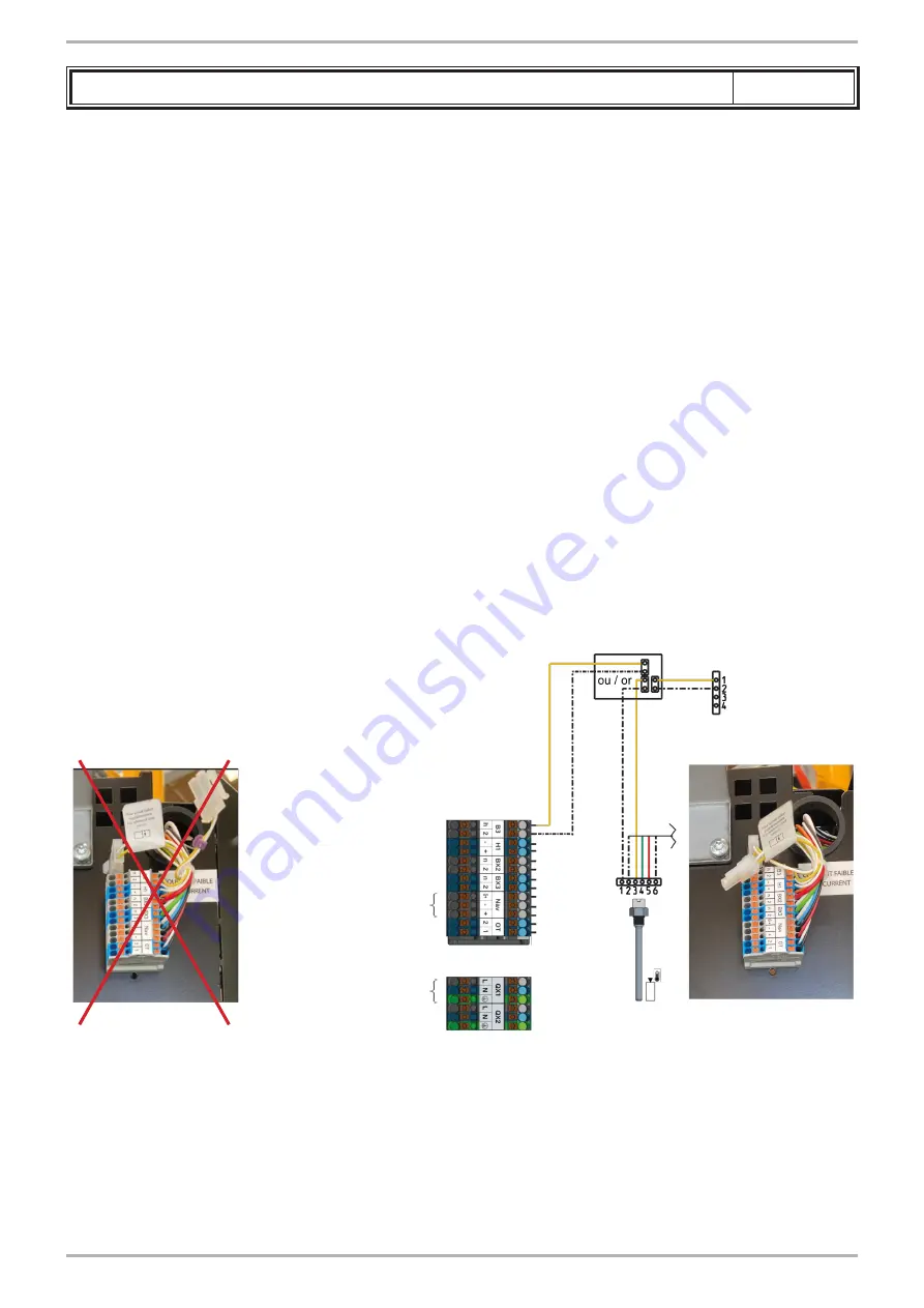
D.
CUSTOMER'S ELECTRICAL CONNECTION
Same electrical connections for DR-SG1 and DR-SG2
Navistem Modbus
(option see § Navipass)
Fault report 230Vac
No modification to
be made
Page 70 / 104
00U07337760-A
DORCHESTER DR-SG -
Installation, Operation and Maintenance