background image

Table of Contents 


IMPORTANT SAFETY INSTRUCTIONS


Safety Information 


Read all instructions. Save these instructions and refer to them

 made. 

This track system is not intended for use with a power supply  
cord or convenience receptacle adaptor. 
This track system must be supplied by a single branch 
120 volt circuit. 

The track is not intended to be pendant mounted such as by a  
stem or cable.


The mounting screws are to be mounted along the track in the  
keyhole slots provided.
Disconnect electrical power before adding to or changing the 

Table of Contents ......................................2
Safety Information ....................................2
Warranty ...................................................

...................................................

3
3
3


.....................................

.....................................

....................................


3

Hardware Included  

.....................................

4

Package Contents  

Pre-Installation


.........................................


Installation
Operation

    g

n

i

n

a

e

l

C


d

n

a


e

r

a

C

........................................8

8

8

5

Troubleshooting ........................................

  SAVE THESE INSTRUCTIONS  

Before energizing, make sure that the lighting system  is clear 
of all material which could cause a direct short, and check all 
electrical connections to make sure they  are secure. 

Do not attempt to energize anything other than EC series track 

tools, extension cords, appliances, etc. to the track. 
Lamp gets hot quickly! Touch only the switch or plug when turning on. Do not touch the hot lamp lens. 

Turn off power and allow bulbs 

to cool down before replacing.


WHEN INSTALLING OR USING THIS TRACK SYSTEM, BASIC SAFETY PRECAUTIONS SHOULD ALWAYS BE FOLLOWED INCLUDING THE 
FOLLOWING: 


WARNING

: Do not install this lighting system in a damp or 

wet location. 


CAUTION:

 To reduce the risk of a burn during re-lamping, 

remove from the track before re-lamping.

CAUTION: 

Hot surface, keep away from curtains or 

any other combustible material.

NOTE:

 All electrical connections must be in accordance with 

local codes and the National Electrical Code. If you are 

 unfamiliar with methods of installing electrical wiring, secure 


CAUTION: 

Refer to the re-lamping label located on the  


IMPORTANT: 

For use with Hampton Bay EC series line  

voltage track systems only. 


Do not install any part of this track system less than 7 ft. 

Do not install any lamps closer than 6 in. from any curtain  
or similar combustible material.

Tools Required


NOTE


:Make sure to install the shade ring  after installed the light

bulb. 

This equipment has been tested and found to comply with the limits for a Class B digital device, pursuant to Part 15 of the FCC Rules. 

These limits are designed to provide reasonable protection against harmful interference in a residential installation. This equipment 

generates, uses and can radiate radio frequency energy and, if not installed and used in accordance with the instructions, may cause 

harmful interference to radio communications. However, there is no guarantee that interference will not occur in a particular 

installation. If this equipment does cause harmful interference to radio ortelevision reception, which can be determined by turning the 

equipment off and on, the user is encouraged to try to correct the interference by one or more of the following measures:  


Reorient or relocate the receiving antenna.  

Increase the separation between the equipment and receiver.

Connect the equipment into an outlet on a circuit different from that to which the receiver is connected. 

Consult the dealer or an experienced radio/TV technician for help.   

Please note that changes or modifications not expressly approved by the party responsible for compliance could void the user’s 

authority to operate the equipment.

FCC responsible party name : Lumitific Corporation ./address: 2850 W Horizon Ridge Parkway #200 Henderson, Nevada United 

States NV89052 /Telephone number: 678-383-4085.

Summary of Contents for EC1577BK-D

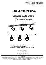
Page 1: ... m EST Monday Friday 9 a m 6 p m EST Saturday Item 1004618676 805259 1004618677 805239 1004612996 805299 1004612982 805279 We appreciate the trust and confidence you have placed in Hampton Bay through the purchase of this lingt fixture We strive to continually create quality products designed to enhance your home Visit us online to see our full line of products available for your home improvement ...

Page 2: ...National Electrical Code If you are unfamiliar with methods of installing electrical wiring secure CAUTION Refer to the re lamping label located on the IMPORTANT For use with Hampton Bay EC series line voltage track systems only Do not install any part of this track system less than 7 ft Do not install any lamps closer than 6 in from any curtain or similar combustible material Tools Required NOTE ...

Page 3: ...ions for proof of purchase Hacksaw NOTE Hardware not shown to actual size The manufacturer warrants this lighting fixture against defects in materials and workmanship for a period of five years from the date of purchase If within this period the product is found to be defective in material or workmanship the product must be returned with a copy of the bill of sale as proof of purchase to the origi...

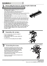
Page 4: ...e Twist lock connector preassembled to mounting plate B Canopy preassembled to mounting plate B Canopy screw preassembled to canopy D Track section Track head Trim preassembled to track head G Connector s locking tab preassembled to track head G Knob preassembled to track head G F G K H I J B A C D E Note Some fixture shapes may vary not shown for all models but the same assembly method ...

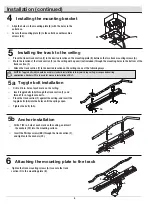
Page 5: ...ire and wire connectors DD back into the outlet box not included B A C D E B F 4 ft or less in length has one mounting opening spaced a maximum of 6 in from each track end section A single section of track that is greater than 4 ft in length must have mounting openings a maximum of 12 in from each end of the track with additional openings a minimum of every 4 ft along the length of the track secti...

Page 6: ... track section F and thread 1 2 in toggle onto bolts Place the track section F against the ceiling and insert the toggle bolts AA into the holes until the springs open Tighten the bolts AA 5a NOTE Toggle bolts AA should be used for standard installation into drywall drop ceiling or suspended ceiling applications Anchors CC are used for masonry installations ONLY Toggle bolt installation Align the ...

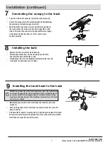
Page 7: ...section F has an indented groove on the face and two internal copper strips The track head G can only be assembled if the ground sides of the track head G connector and the track section F are aligned Identify the ground side on the track head G connector and track section F Push the top portion of the track head G connector into the slot of the track section F Pull down the connector s locking ta...

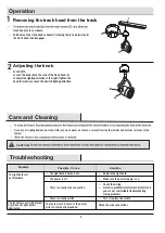
Page 8: ...terior and exterior surfaces of the Troubleshooting The fuse blows or circuit breaker trips when the light bulb is illuminated The light bulb is burned out The power is off Replace the light bulb Check the wiring you are not comfortable troubleshooting wiring problems Test or replace the switch track head G to cool down Pull down on the track head connector s locking tab J and twist until the trac...

Page 9: ... this manual for future use 1 855 HD HAMPTON HAMPTONBAY COM Questions problems missing parts Before returning to store call Hampton Bay Customer Service 7 a m 6 p m EST Monday Friday 9 a m 6 p m EST Saturday ...

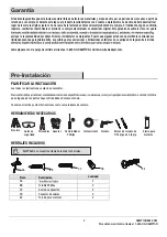
Page 10: ...roductos disponibles para las necesidades de mejoras de tu hogar Gracias por elegir Hampton Bay 1 855 HD HAMPTON Preguntas problemas o piezas faltantes Antes de regresar a la tienda llama al servicio al cliente de Hampton Bay de lunes a viernes de 7 a m a 6 p m hora estándar del Este y sábados de 9 a m a 6 p m hora estándar del Este HAMPTONBAY COM EC8715BK D EC8715WH D EC1577BK D EC1577WH D Modelo...

Page 11: ...se deben hacer conforme con el en un lugar húmedo durante el cambio de las bombillas desmonta la lámpara del riel antes de cambiar la bombilla las cortinas y otros materiales combustibles Consulta la etiqueta para cambio de PRECAUCIÓN Código Nacional de Electricidad y con los códigos de electricidad locales Si no estás familiarizado con los métodos de instalación del cableado eléctrico contrata lo...

Page 12: ...efectos en materiales y mano de obra por un periodo de cinco años a partir de la fecha de su compra Si durante este lapso el producto resulta defectuoso en cuanto a material omano de obra deberá devolverlo al lugar de la compra original junto con una copia de la factura de venta comocomprobante de la compra El fabricante según su criterio reparará sustituirá o reembolsará el precio de la compra al...

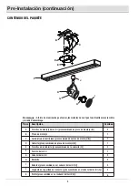
Page 13: ...ca de montaje B Cubierta preensamblado de placa de montaje B Tornillos de la Cubierta preensamblado de la cubierta D Sección del carril Cabezal del carril Reborde preensamblado en el cabezal del carril G Lengüeta de seguridad del conector preensamblado en el cabezal del carril G Perilla preensamblado en el cabezal del carril G Remarque A forme des luminaires peut varier les modèles ne sont pas tou...

Page 14: ... largo debe tener una abertura de 12 plg 300 mm para el montaje como máximo desde cada extremo del riel con aberturas adicionales cada 4 pies 1 22 m a lo largo de todo el riel Las aberturas adicionales cada 4 pies 1 22 m a lo largo de la sección del riel se deben agregar según sea necesario Retire los tornillos de la cubierta E del cubierta D para exponer la placa de montaje B B A C D E Desliza la...

Page 15: ...iones en mampostería Instalar el perno acodado la caja de salida B F A 5b Instalación de los anclajes 6 BB F CC Inserte los tornillos Phillips BB a través de la sección del carril F y apriete las anclas de expansión CC Fijar la placa de montaje al riel Apriete los tornillos de montaje A del carril para asegurar la sección del carril lineal F a la placa de montaje B montaje EE B Coloque la sección ...

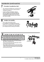
Page 16: ...engüetas de metal El lado de puesta a tierra de la sección del carril F tiene una ranura dentada en la parte frontal y dos tiras de cobre internas El cabezal del carril G sólo se puede ensamblar si los lados con puesta a tierra del cabezal del carril G y la sección del carril F están alineados J del carril G y la sección del carril F Presione la parte superior del conector del cabezal del carril G...

Page 17: ...bombilla Revisa el cableado solución de problemas del cableado Prueba o reemplaza el interruptor Jale hacia abajo la lengüeta de bloqueo del conector J del cabezal del carril y gire hasta que el cabezal del carril G se libere Para retirar el cabezal del carril G de la sección del carril F primero permita que se enfríe el cabezal del carril G Para limpiar la lámpara desconecta primero la electricid...

Page 18: ...s de regresar a la tienda llama al servicio al cliente de Hampton Bay de lunes a viernes de Conserva este manual para uso en el futuro 7 a m a 6 p m hora estándar del Este y sábados de 9 a m a 6 p m hora estándar del Este HAMPTONBAY COM VAHD1577 004 v 1 2019 10 ...

Reviews: