5
Installation
1
2
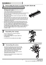
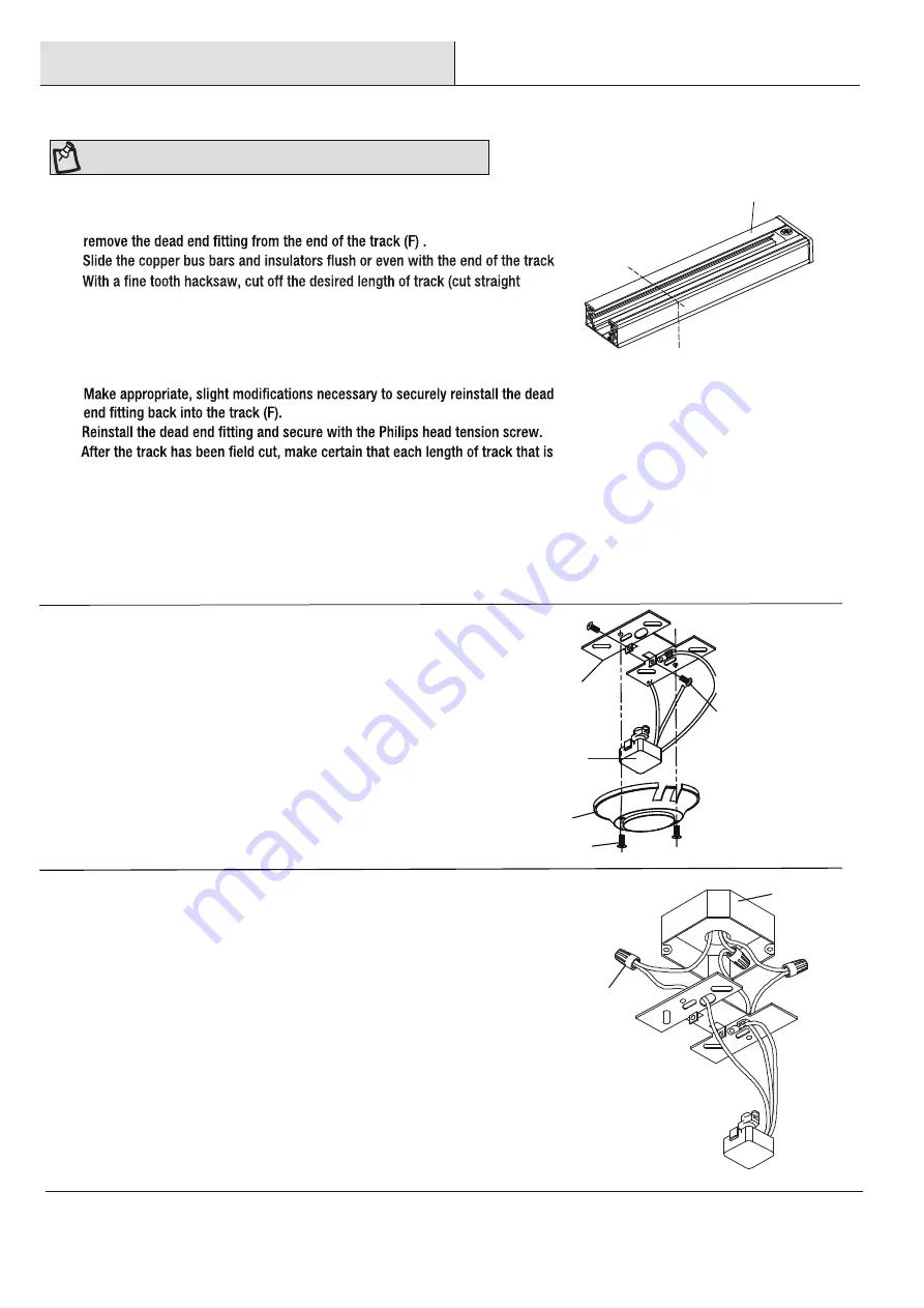
Loosen the track mounting screws (A) preassembled to the
mounting plate (B).
Do not remove the track mounting screws (A) completely.
Field cutting the track to special lengths (Optional)
Separating the canopy
NOTE:
Cutting should be done preferably from the dead end of the track.
□
□
□
Remove the canopy screws (E) from the canopy (D) to
expose the mounting plate (B).
3
DD
Outlet Box
Connecting the wires
□
□
□
Connect the wires (white wires from connector to the white
wires from the supply circuit, black wires from the connector
to the black wires from the supply circuit, and the green
ground wire from the connector to the ground wire of the
supply circuit) using the wire connectors (DD).
Wrap electrical tape (not included) around wire connectors
(DD) and make sure they are secure.
Push all excess wire and wire connectors (DD) back into the
outlet box (not included).
B
A
C
D
E
B
F
□
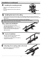
4 ft. or less in length has one mounting opening spaced a maximum of 6 in.
from each track end section. A single section of track that is greater than 4 ft.
in length must have mounting openings a maximum of 12 in. from each end of the
track with additional openings a minimum of every 4 ft. along the length of the
track section. Additional openings every 4 ft. along the track section may
be added as needed.
□
□
□
□
□
□
□
□
(F)
.
down through the track).
Remove all burrs from the track, insulators, and copper bus bars so the end
is smooth to the touch.
Slide the copper bus bars and insulators back into the track leaving approx. ¼ in
space between the end of the track and the insulator, copper bus bar assembly.
Align the track so the open side is facing upward (the side where
the copper bus bars are exposed).
Using a Philips head screwdriver, loosen the tension screw and
HAMPTONBAY.COM
Please contact 1-855-HD-HAMPTON for further assistance.

