


shows the vibrato circuit.
1. THEORY OF OPERATION
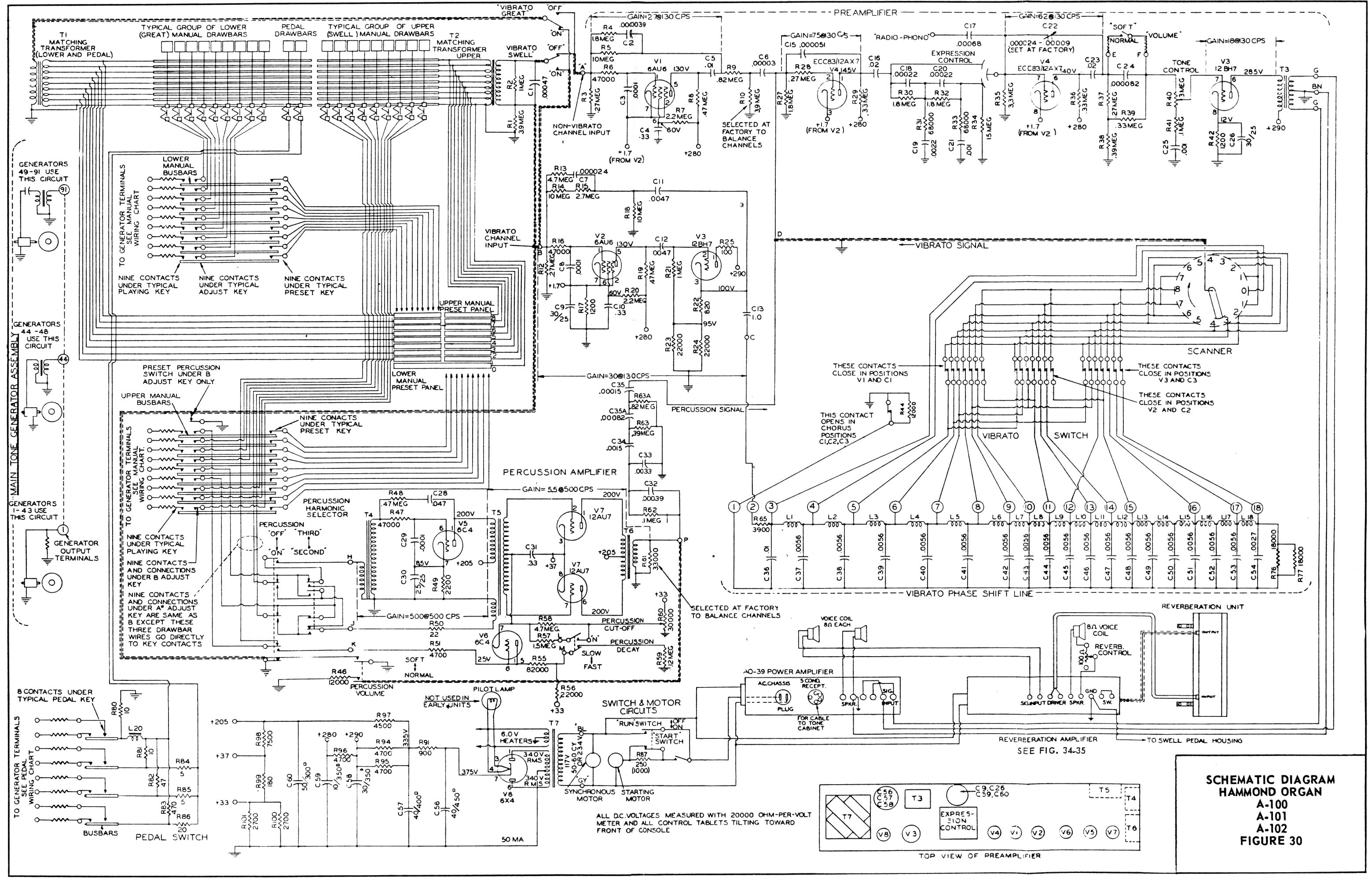
The percussion tones are produced by borrowing the 2nd or 3rd harmonic signal from the
corresponding drawbar (of the upper manual "B " adjust key drawbar group), amplifying it,
returning part of it to the same drawbar, and conducting the balance through push-pull
control tubes, which when keyed cause the signal to fade away at a pre-determined rate.
2. GENERAL CIRCUIT OPERATION (All Reference Is To Schematic diagram - End of
Book.)
With percussion tablet "on" upper manual "B" adjust key and an upper manual playing key
pressed, the 2nd or 3rd harmonic signal appearing on an upper manual busbar is
conducted through "B" adjust key drawbar wire to input of percussion amplifier (terminal H)
and amplified by T4 and V5. Besides providing push-pull signal for the control tube V7, the
percussion input transformer T5 has a third winding which feeds the signal back to the 2nd
or 3rd harmonic drawbar through equivalent key circuit resistor R50 and terminal J. Thus
the signal that was borrowed from the 2nd or 3rd harmonic drawbar for the percussion
amplifier is replaced.
When a key is depressed the signal first sounds loudly through the control tube,
transformer T6, a high pass filter, and terminal D to the grid of V4. Immediately condenser
C31 in the control tube grid circuit begins to discharge, causing the signal to fade away.
This circuit works as follows: Terminal K (approxi25 volts) is connected to the 8th
harmonic "B " adjust key drawbar wire which is connected to the manual busbar. Pressing
any upper manual key grounds terminal K through the tone generator filters. This virtually
grounds the plate of Vb (connected as a diode), stops conduction, and isolates cathode
and control tube grid circuits. The grid then drifts from approxi25 volts to about
+15 volts, at a rate determined by the time required for C31 to discharge through R57 and
R58. At the completion of this sequence, the percussion signal is blocked. No further
percussion effects occur until all keys of the upper manual are released and control grids
can again rise to +25 volts. The rate of this rise is fixed by the time required to charge C31
to +25 volts through R55 and R56.
23
tuttotastiere.com


