background image

PAGE    OF

REV.

BUL86874

C

9

HWM - SERIES

INSTRUCTIONS FOR

HWM

2

vis it our website:
vis itez notre site Web:

www .hammondmfg.com

IMPORTANT SAFETY CAUTIONS

NOTE: Read all inst ructions  before inst alling and usin g the product.

LOADING RACK SYSTEM

NOTE: When loading equipme nt into the enclosu re or
rack syste m ensu re weight is dist ributed so  that heavier
loads  are placed towards  the bottom of the rack to
avoid unst able conditions.

The foll owin g parts  are not  effect ively b onded t o t he  Pro tectiv e Earth
Terminal ( PET):  Mou nting r ails,  Mid Secti on,  and D oo r. If a ny  part
need s t o be bo nded t o t he  PET it s hall  be done i n acc ordance wit h
Arti cl e 25 0 of t he N atio nal Elect ric  Code.

To redu ce ri sk  of  perso nal i njury a nd p roduct  dama ge always  ensure a
a suffici ent  amou nt  of  personne l are present  when l oading,  unloa ding,
and mov in g t he encl osure or  rack  syst em.

Ev enly d ist ribute  all  mounted l oads  and equipment t o e nsure st ability
within  t he syst em.

Always fu lly  m ount  and s ecu re encl osure  or rack  syst em  bef ore  loading
equipment.

Ensure unit i s  plumb an d lev el fo r  proper  opera tion.

Rou te all  chords  an d cables  away fr om  mov ing pa rts  and all  poss ible
pinch points.

En sure t hat t he flo or/ wall st ruct ure is  able t o  withst and t he weight  of
the c abin et  while fully l oad ed.

I nst allatio n and ass embly m u st  be perfo rmed by  qualifi ed pe rsonnel.

350 lb

Maximu m W eight Capacity:

Suit able  for  m ounting  on concr et e or ot her no ncomb usti b le s urfa ce only.

Summary of Contents for HWM Series

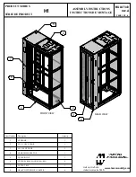
Page 1: ... REV BUL86874 C 9 HWM SERIES INSTRUCTIONS FOR HWM 1 visit our website visitez notre site Web www hammondmfg com 1 2 3 Item Number Title Quantity 1 HWM DOOR ASSY 1 2 HWM CENTRE SECTION 1 3 HWM REAR MOUNT ASSY 1 ...

Page 2: ...Arti cl e 250 oft he National Electric Code To reduce ri sk of personal i njurya nd product damage always ensure a a suffici ent amount of personnel are present when l oading unloading and mov ing the encl osure or rack syst em Ev enlyd ist ribute all mounted l oads and equipmentt o ensure st ability within the syst em Alwaysfu lly mount and s ecure encl osure or rack syst em before loading equipm...

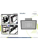
Page 3: ...INSTRUCTIONS FOR HWM 3 visit our website visitez notre site Web www hammondmfg com 1 TOOL BOX LEV EL NIVEAU WALLMOUNT INSTRUCTIONS OPTIONAL Remove front section of wallmount to allow for an easier install INSTALL WITH NYLONSTRIP ATBOTTOM ...

Page 4: ...als require different types of screws Mount back pan using 3 8 dia lag bolts and standard flat washers FRANÇAIS Les différents matériaux de paroi murale nécessitent différents types de vis Monter l arrière du boîtier à l aide de tire fond de 3 8 po de diamètre et de rondelles plates standard INSTALL WITH NYLON STRIP ATBOTTOM ...

Page 5: ...HWM SERIES REV BUL86874 C INSTRUCTIONS FOR HWM PAGE OF 9 5 4 ...

Page 6: ...HWM SERIES REV BUL86874 C INSTRUCTIONS FOR HWM PAGE OF 9 6 REVERSE MIDDLE SECTION INSTRUCTIONS 1 2 3 180v ...

Page 7: ...ECTION SHALL BE ATTACHED TO FIGURE 1 NOTE ALL PROTECTIVE EARTH AND BONDING CONNECTIONS SHALL BE IN ACCORDANCE WITH ARTICLE 250 OF THE NATIONAL ELECTRIC CODE 1 Included within optional grounding kit GRDKIT01 2 x Bonding Wire 10 Gauge 1 4 Ring Terminals 4 x 10 32 Phillips Screw Pan Head 4 x 10 32 Locking Nut 4 x 1 4 Flat Washer 4 x 1 4 20 Slotted Screw Pan Head 4 x 1 4 20 Locking Nut 4 x 10 Flat Was...

Page 8: ...ction Attach bonding wire found in ground kit to a centre section bonding stud closes t to the hinged side of the enclosure using the ring terminal and hardware provided Attach opposite end of wire to the nearest PET on the rear section Door Attach bonding wire to the door stud using the same method described above Attach the opposite end to the nearest centre section bonding stud Bonding Connecti...

Page 9: ...openings allow for cable entry mounting of conduits and fan mounting Proper Removal of Knock Outs When removing an inner knock out with the intent to leave the larger in tact ensure the force is applied to the weakest area of the ring This is accomplished by placing the knock out tool as far away from the tabs as possible while remai ning as close to the tab of the next largest ring shown to the l...

Reviews: