


0
Subject to change without notice
Practical Selection of
Signal-Line Filters
The steadily increasing operating speed of mo-
dern digital logic causes significantly greater
concerns with EMC problems. This has become
more noticed by all manufacturers of electrical
and electronic devices since 1 January l996, the
effective compliance date for the European Union
EMC Directive. The EMC Directive does not cause
the radiated interference problems, but it causes
conflict with the requirements of compliance for
each manufacturer.
The times are long gone when the EMC problems
could be left to the EMC department or a non-
compliant product was not noticed and could be
sold anyhow. Every circuit designer must at the
beginning of a development be aware of potential
EMC problems to even allow the successful cer-
tification of a product. Printed circuit boards must
be built differently than was possible several years
ago. A reasonable broadband decoupling of the
supply voltages is the present state-of-the-art.
But also the design of signal lines must be con-
sidered and can not be left to chance. Digital
signals have a spectrum with a bandwidth, B, that
is related by:
B = 1 / (.1 • tr),
where tr is the risetime.
Consequently, the risetime of a digital signal tran-
sition is the determinant. The shorter the risetime,
the wider the frequency range. However, the
calculated bandwidth is not as important as the
one that actually exists which can be significantly
different than the calculated one. The reason for
this is that the calculated value is referenced to
a capacitive total load. For most practical cases
this does not occur. An approximate calculation
shows that one half of the capacitive load means a
twice faster risetime; e.g. a microprocessor has a
specified risetime of x 10
-9
s (ns). The capacitive
load is supposed to be 150 pF. If a signal from this
processor is loaded only with a CMOS gate of 1.5
pF, the risetime will be 1 times faster and a value
of 00 x 10
-1
s (00ps) must be expected. In the
frequency domain, 00ps is equivalent to a band-
width of 1.6 GHz. Even in practical circuits, where
additional capacitance can be expected, actual
bandwidths of over 1GHz are measurable.
From an EMC point of view, this is naturally very
damaging. The actual risetime in CMOS circuits
is not easily measurable in most digital labs. To
measure the actual risetimes, oscilloscopes with
the ability to measure 100ps (10E-10s) or smaller
must be used. Such oscilloscopes are available
but at a significant price.
A practical solution is to perform the measure-
ments in the frequency domain: The digital func-
tion is observed with a „slower“ and economical
oscilloscope and the relevant EMC characte-
ristics are measured with a spectrum analyzer.
Since the spectrum analysis of corresponding
frequency ranges is technically simpler than the
measurement of the equivalent risetimes, basic
spectrum equipment can be obtained which is
relatively more economical. Spectrum analyzers
with a bandwidth of 1,000MHz are already suitable
for analyzing CMOS circuits. The corresponding
oscilloscopes are still very expensive.
Spectrum analyzers are high frequency equip-
ment and have therefore an input impedance of
50 Ohms. They are therefore not suitable to
Practical Selection of Signal-Line Filters
P r a c t i c a l S e l e c t i o n o f S i g n a l - L i n e F i l t e r s
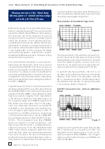
Figure 1


