M2503 VIDEO BOOSTER
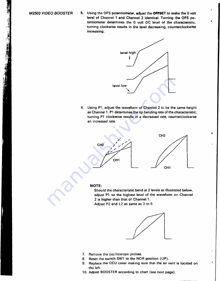
5. U s i n g the OFS potentiometer, adjust the OFFSET to make the 0 volt
level of Channel 1 a n d Channel 2 identical. Turning the OFS po-
tentiometer determines the 0 volt D C level o f the characteristic,
turning clockwise results in the level decreasing, counterclockwise
increasing.
level high
level low
6. U s i n g P1, adjust the waveform of Channel 2 to be the same height
as Channel 1. P1 determines the tip bending rate of the characteristic;
turning P1 clockwise results in a decreased rate, counterclockwise
an increased rate.
NOTE:
Should the characteristic bend at 2 levels as illustrated below,
adjust P1 so the highest level of the waveform on Channel
2 is higher than that of Channel 1.
Adjust P2 and L2 as same as 3 to 6.
7. R e m o v e the oscilloscope probes.
8. R e s e t the switch SW1 t o the NOR position (UP).
9. R e p l a c e the CCU cover making sure that the air vent is located on
the left.
10. Adjust BOOSTER according to chart (see next page).


