
P29 Instruction Manual
19
Hysteresis
This item can be used to select the hysteresis for the particular warning. The action described
in 7.3.1 applies to the entry unit. The hysteresis is always positive.
Tv delay time
The entry value of the warning is derived from the unfiltered pressure value. With this
parameter, you can now specify how long the pressure value can be exceeded or not met until
the warning is activated. The adjustment is done in ms. 25 ms is specified as the minimum
value.
Tn follow-up time (from Rev2.11)
The entry value of the warning is derived from the unfiltered pressure value. With this
parameter it can now be specified how long the warning remains activated after the pressure
value is again within the range in which the warning is not active. The adjustment is done in
ms.
Warning signal
A warning signal sounds once every second when a threshold value is exceeded. With this
parameter, you can set the duration of this warning signal for each warning. The maximum
value here is 1000 ms (continuous tone). If both warnings are active, the longer warning signal
of the two sounds. The warning signal may sound different depending on the activation level.
A warning signal duration of 0 ms switches the signal off.
Filter (from Rev2.14)
This item can be used to adjust whether the warning is to be activated when the pressure
exceeds or falls below the warning pressure threshold. This affects the processing of the
hysteresis value.
7.4 Settings
With this menu item, you can adjust various parameters that affect the instrument’s behaviour.
The following sub-menu items are available:
Language
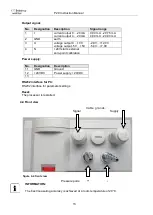
Output
Filter
Warning signal
Resolution
Zero-point calibration
CS (creep suppression)
Lightning
Colour change
Brightness
Contrast
Read factory settings
Code?
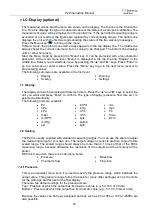
Language
The menu language can be selected with this menu item. You can choose from the following
languages:
English
German
Italian
French
Make your choice with the
“▲“ or “►“ keys. Press Enter to confirm your selection.