3.20
FILLING A SEALED WATER SYSTEM
Provision for filling the system at low level must be made, see
figure 8. There must be no permanent connection to the mains
water supply, even through a non-return valve.
CONTROLS. As a minimum it is recommended that a room
thermostat be installed to control the appliance. Thermostatic
radiator valves may be fitted to the system, however they must not
be fitted in the room where the room thermostat is fitted. There must
be at least one radiator installed with lock shield valves that should
not be closed. Further guidance can be obtained from the Domestic
Heating and Hot Water Guide to the building regulations.
13
3.21
ELECTRICITY SUPPLY
a)
Wiring external to the appliance must be in accordance with
the current I.E.E Wiring regulations (BS 7671) for electrical
installation and any local regulations, which apply.
b)
The mains cable must be at least 0.75 mm2 (24/0.2 mm)
PVC insulated to BS 6500 table 16.
c)
THIS APPLIANCE MUST BE EARTHED. Failure to provide a
satisfactory earth connection will result in appliance malfunction.
3.22
EXTERNAL CONTROLS
The VBX appliances may be used with any certified
programmer/room thermostat, as described in section 4. For
further information contact: Halstead Boilers Ltd, Service Helpline:
01926 834834.
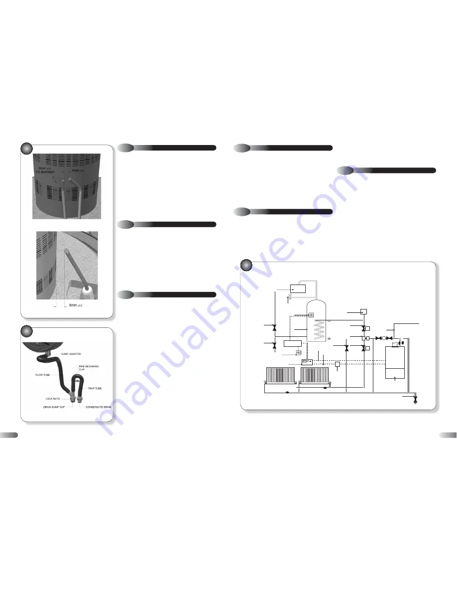
DRAIN
AUTOMATIC
AIR VENT
FLOW
RETURN
TANK
THERMOSTAT
ROOM
THERMOSTAT
TERMINAL
BLOCK
MOTORISED
VALVE
LOCKSHIELD
VALVE
STOP
VALVE
DRAIN
MOTORISED
VALVE
COLD
FEED
3-WAY
VALVE
TO DRAIN
OFF TAP
HOT WATER
CYLINDER
COLD WATER
STORAGE
APPLIANCE
CH SWITCH
DIRECT HW
CONNECT
CH/DHW
2 CHANNEL
PROGAMMER
220V RELAY BOX
(Optional)
8
OPEN WATER SYSTEM
d)
The method of connection to the mains supply must facilitate
complete electrical isolation of the appliance. Either a 3A fused
three pin plug and un-switched shuttered socket outlet, both
complying with BS 1363, or a 3A fused double pole switch
having a 3 mm contact separation in both poles and serving only
the boiler (and its external controls) may be used.
NOTE:
No automatic by-pass required. However it is
recommended to leave one radiator open and to fit a
system bypass in the DHW circuit to ensure pump over-
run functionality.
24
29A SPARK ELECTRODE
29 B DETECTOR ELECTRODE
30
CONDENSATE DRAIN
6.7
SEALED WATER SYSTEM
a)
Check the operation of the pressure relief valve as described
in section 5.1 (b).
b)
Check the correct operation of the pressure gauge by noting
the reading when cold and check that the pressure increases with
temperature. Replace the gauge if readings are suspect.
c)
Check that the system is at its original (cold) design pressure.
If necessary, re-pressurise the system as described in section 5.1
(b) and search for and rectify any leaks causing loss of water.
d)
In case of heavy pressure fluctuations during the heat and
cool down cycle, check the pre-charge pressure of the expansion
vessel. If the air pressure is less than 0.75 bar recharge vessel
with an air pump.
6.8
RE-ASSEMBLY & RE-COMMISSIONING
a)
Re-assemble all components in reverse order.
b)
Check that all joints and seals are correctly fitted.
c)
Turn on the gas and electricity supply and light the appliance,
as described in section 5.2.
d)
Re-perform a combustion check, as described in section 6.1.
e)
Check the operation of the appliance in CH mode.
f)
Remove the manometer and tighten the inlet pressure test
point sealing screw.
g)
Test for gas tightness.
6.9
FINAL CHECKS
a)
Ensure the sealed chamber door is secure with the six fixing
screws.
b)
Re-fit all decorative casing panels.
c)
Return all appliance and external controls (if fitted) to their
original settings.
29


